×
ToyotaParts- Hello
- Login or Register
- Quick Links
- Live Chat
- Track Order
- Parts Availability
- RMA
- Help Center
- Contact Us
- Shop for
- Toyota Parts
- Scion Parts
My Garage
My Account
Cart
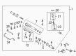
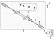
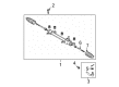
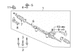
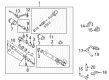
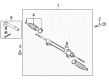
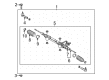
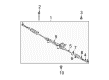
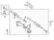
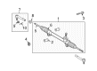
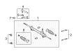
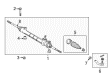
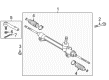
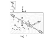
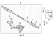
OEM Toyota Rack And Pinion
Steering Gear- Select Vehicle by Model
- Select Vehicle by VIN
Select Vehicle by Model
orMake
Model
Year
Select Vehicle by VIN
For the most accurate results, select vehicle by your VIN (Vehicle Identification Number).
338 Rack And Pinions found


Toyota Steering Gear Part Number: 44250-35042
$547.17 MSRP: $801.89You Save: $254.72 (32%)Ships in 1-3 Business DaysProduct Specifications- Other Name: Gear Assembly, Power Steering; Rack and Pinion Assembly; Steering Gearbox; Gear Assembly; Gear Assembly, Power Steering(For Rack & Pinion)
- Replaces: 44250-35041, 44250-35040


Toyota Steering Gear Part Number: 45510-02490
$568.96 MSRP: $833.82You Save: $264.86 (32%)Ships in 1-2 Business DaysProduct Specifications- Other Name: Gear Assembly, Steering; Rack and Pinion Assembly; Steering Gearbox; Rack & Pinion; Gear Assembly


Toyota Steering Gear Part Number: 45510-02171
$628.55 MSRP: $921.15You Save: $292.60 (32%)Ships in 1-3 Business DaysProduct Specifications- Other Name: Gear Assembly, Steering; Rack and Pinion Assembly; Steering Gearbox; Gear Assembly
- Replaces: 45510-02170


Toyota Steering Gear Part Number: 44200-60170
$763.96 MSRP: $1119.59You Save: $355.63 (32%)Ships in 1-3 Business DaysProduct Specifications- Other Name: Link Assembly, Power Steering; Rack and Pinion Assembly; Steering Gearbox; Gear Assembly; Steering Gear Assembly


Toyota Gear Assembly, Power Steering(For Rack & Pinion) Part Number: 44250-60050
$685.64 MSRP: $1004.81You Save: $319.17 (32%)Ships in 1-3 Business DaysProduct Specifications- Other Name: Gear Assembly, Power Steering; Rack and Pinion Assembly; Steering Gearbox


Toyota Steering Gear Part Number: 45510-06011
$568.96 MSRP: $833.82You Save: $264.86 (32%)Product Specifications- Other Name: Gear Assembly, Steering; Rack and Pinion Assembly; Steering Gearbox; Gear Assembly
- Replaces: 45510-06021


Toyota Rack & Pinion Part Number: 44250-35080
$653.07 MSRP: $957.08You Save: $304.01 (32%)Ships in 1-3 Business DaysProduct Specifications- Other Name: Gear Assembly, Power Steering; Steering Gearbox; Gear Assembly, Power Steering(For Rack & Pinion)


Toyota Link Assembly, Power Steering Part Number: 44200-35061
$653.07 MSRP: $957.08You Save: $304.01 (32%)Ships in 1-3 Business DaysProduct Specifications- Other Name: Steering Gearbox
- Replaces: 44200-35060


Toyota Link Assembly, Power Steering Part Number: 44200-60100
$680.83 MSRP: $997.77You Save: $316.94 (32%)Product Specifications- Other Name: Rack and Pinion Assembly; Steering Gearbox


Toyota Steering Gear Part Number: 44250-04040
$750.56 MSRP: $1099.96You Save: $349.40 (32%)Product Specifications- Other Name: Gear Assembly, Power Steering; Rack and Pinion Assembly; Steering Gearbox; Rack & Pinion; Gear Assembly; Gear Assembly, Power Steering(For Rack & Pinion)


Toyota Steering Gear, Driver Side Part Number: SU003-00841
$230.47 MSRP: $306.02You Save: $75.55 (25%)Ships in 1-2 Business DaysProduct Specifications- Other Name: Gear Box Assembly M/S Left-Hand; Rack and Pinion Assembly; Steering Gearbox; Gear Assembly; Gear Assembly, Steering
- Position: Driver Side


Toyota Steering Gear Part Number: 45510-0E030
$628.55 MSRP: $921.15You Save: $292.60 (32%)Ships in 1-3 Business DaysProduct Specifications- Other Name: Gear Assembly, Steering; Rack and Pinion Assembly; Steering Gearbox; Gear Assembly
- Replaces: 45510-48010


Toyota Steering Gear Part Number: 44250-06330
$653.07 MSRP: $957.08You Save: $304.01 (32%)Ships in 1-3 Business DaysProduct Specifications- Other Name: Gear Assembly, Power Steering; Rack and Pinion Assembly; Steering Gearbox; Rack & Pinion; Gear Assembly; Gear Assembly, Power Steering(For Rack & Pinion)


Toyota Steering Gear Part Number: 44200-35094
$773.15 MSRP: $1133.06You Save: $359.91 (32%)Ships in 1-2 Business DaysProduct Specifications- Other Name: Link Assembly, Power Steering; Rack and Pinion Assembly; Steering Gearbox; Rack & Pinion; Gear Assembly
- Replaces: 44200-35092, 44200-35090, 44250-35090, 44200-35093, 44200-35091


Toyota Steering Gear Part Number: 45510-0T011
$567.15 MSRP: $831.16You Save: $264.01 (32%)Product Specifications- Other Name: Gear Assembly, Steering; Rack and Pinion Assembly; Steering Gearbox; Gear Assembly
- Replaces: 45510-0T010


Toyota Steering Gear Part Number: 45510-08020
$567.15 MSRP: $831.16You Save: $264.01 (32%)Ships in 1-3 Business DaysProduct Specifications- Other Name: Gear Assembly, Steering; Rack and Pinion Assembly; Steering Gearbox; Rack & Pinion; Gear Assembly


Toyota Steering Gear Part Number: 45510-12640
$568.96 MSRP: $833.82You Save: $264.86 (32%)Ships in 1-3 Business DaysProduct Specifications- Other Name: Gear Assembly, Steering; Rack and Pinion Assembly; Steering Gearbox; Gear Assembly


Toyota Steering Gear Part Number: 45510-07010
$568.96 MSRP: $833.82You Save: $264.86 (32%)Ships in 1-3 Business DaysProduct Specifications- Other Name: Gear Assembly, Steering; Rack and Pinion Assembly; Steering Gearbox; Rack & Pinion; Gear Assembly


Toyota Gear Assembly Part Number: 44250-0C160
$556.03 MSRP: $814.86You Save: $258.83 (32%)Ships in 1-3 Business DaysProduct Specifications- Other Name: Gear Assembly, Power Steering; Rack and Pinion Assembly; Steering Gearbox; Steering Gear Assembly
- Replaces: 44250-0C070, 44250-0C100


Toyota Steering Gear Part Number: 44250-04041
$663.17 MSRP: $971.88You Save: $308.71 (32%)Product Specifications- Other Name: Gear Assembly, Power Steering; Rack and Pinion Assembly; Steering Gearbox; Rack & Pinion; Gear Assembly; Gear Assembly, Power Steering(For Rack & Pinion)
| Page 1 of 17 |Next >
1-20 of 338 Results
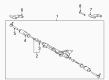
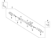
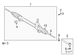
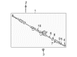
Toyota Rack And Pinion
OEM parts deliver unmatched quality you can rely on. They pass extensive quality control inspections. Toyota produces them to the official factory specifications. This process helps prevent defects and imperfections. So you can get exceptional lifespan and a flawless fit. Need new OEM Toyota Rack And Pinion? You'll love our wide selection of genuine options. Shop in minutes and skip the hunt. Our prices are unbeatable, you'll save time and money. It's easy to shop and find the right piece. Our committed customer service team gives professional help from start to finish. Every part includes a manufacturer's warranty. We ship quickly, your parts will arrive fast at your door.
Toyota Rack And Pinion is a transformation of small steering wheel twists into quick and certain wheel turns to be confidently controlled. Toyota continues to cut fat on each assembly line, resulting in the hybrids guzzling less fuel, its batteries, and its new TNGA platform using fewer materials and less weight and increasing its crash protection without compelling its drivers to drive slowly or accept compromised handling. Toyota won the world over by demonstrating that hard paint, small panel space, and components of the drive train which last longer than the finance payment can coexist with plug-in systems that roll away on electricity alone, even during wars, recessions, and fluctuating fuel prices. The same lean philosophy is directed at Toyota, whether it is a small hatchback or a monster SUV. Shoppers can expect the same thing, namely predictable reliability, smoothness during the drive, and low cost of ownership regardless of the badge they choose. As the wheel rotates, the Rack And Pinion moves a toothed bar to the right or left and Toyota complements that motion with the aid of high pressure fluids to ensure steering remains light at parking speed and stiffens up on the highway to provide clean lane feedback and a consistent on-center feel even after years of real-world jolts. A Rack And Pinion with a fresh seal is tighter and the gears are accurate without the wander-like wander. Go with a fresh Rack And Pinion when the first signs of fluid leaking or unbalanced tie-rod action appear to replace a worn one and get crisp turn-in again and tire life insurance.
Toyota Rack And Pinion Parts and Q&A
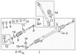
- Q: How to Overhaul the Rack And Pinion in a Power Steering Link Assembly on Toyota 4Runner?A:The Power Steering Link Assembly overhaul process starts with disconnecting the negative terminal of the battery while keeping the front wheels oriented straight ahead. Begin by detaching these components in order: horn button assembly followed by steering wheel assembly with Special Service Tool 09950-50013 and its variations, steering column cover lower, turn signal switch assembly, spiral cable sub-assembly, front wheel, engine under cover assembly rear and engine under cover sub-assembly No.1. The next step requires you to uninstall the stabilizer bar front while separating the tie rod end sub-assembly LH by taking off its cotter pin and nut then applying Special Service Tool: 09628-62011 to detach the sub-assembly from the steering knuckle arm. A similar process must be followed on the right-hand side assembly. The same process needs application on the RH side. The technician should disconnect the pressure feed tube assembly using Special Service Tool: 09023-12700 followed by disconnecting the rack and pinion outlet return tube with Special Service Tool: 09023-12701 while removing the steering intermediate shaft sub-assembly No.2 from the system. The removal of the power steering link assembly demands you to unscrew 2 bolts and 2 nuts but be aware you should turn the bolts rather than the nuts. Remove the power steering link assembly by first using Special Service Tool: 09023-38201 to disconnect two turn pressure tubes followed by a vise installation using Special Service Tool : 09612-00012. Disassemble the LH and RH tie rod end sub-associations then detach both steering rack boot clamps and clips from both sides with caution toward the boots. Begin by unstaking the washer on the rack and pinion end sub-assembly while steadying the rack with a spanner and using Special Service Tool: 09922-10010 to detach the rack end. Special Service Tool: 09922-10010 along with a hexagon wrench (24 mm) can be used to remove the rack guide and spring. The power steering control valve can be removed by unlocking 2 bolts before pulling out the assembly and removing the O-ring. Mount the control valve assembly into a soft jaw vise before using Special Service Tool: 09631-20060 to remove the bearing guide nut without damaging the oil seal lip. Use Special Service Tools 09950-60010 (00951-00300) and 09950-70010 (00951-07100) with a hammer to drive out the oil seal from its position. This operation needs to be followed by separating the teflon rings and union seat. Special Service Tool: 09950-70010 (09951-07150), 09950-60010 (09951-00250) needs to be used for pressing out the bearing and oil seal at the power steering control valve upper oil seal. To remove the cylinder end stopper and O-ring you need Special Service Tool: 09631-20120 followed by rack and pinion and oil seal extraction using Special Service Tool: 09950-70010 (09951-07200). The power steering rack needs to be inspected for clogging before performing checks on the proper torque for tie rod end sub-assemblies LH and RH. Coat the new O-ring along with teflon ring in power steering fluid before adding them to the rack and pinion piston ring. Apply power steering fluid onto Special Service Tool: 09631-00350 before you install the rack and its compatible oil seal in the correct manner. To finish the repair process you should use Special Service Tool: 09631-20120 to torque the cylinder end stopper to 145 Nm (1,479 kgf-cm, 107 ft. lbs.) while utilizing the new O-ring then verify vacuum stability through Special Service Tool: 09631-12071 (09633-00010).
- Q: How to Service and Repair a Rack And Pinion System on Toyota Tacoma?A:Begin the rack and pinion servicing by using Special Service Tool: 09023-38200 to remove 2 turn pressure tubes and then proceeding to the removal of 2 union seats from both rack housing and control valve housing. The Rack And Pinion assembly requires special installation into a vise using Special Service Tool: 09612-00012 and 2 bolts (Bolt: 90105-10346, Nut: 90170-10198). Start the procedure by marking both tie rod ends and rack ends before unfastening the lock nuts to take off both right-hand side and left-hand side tie rod ends. The technician should next eliminate the RH and LH clips alongside rack boots and clamps but should maintain boot integrity. Use a screwdriver as well as a hammer to unstake claw washers before securing the rack and pinion with a spanner to detach the rack ends by using Special Service Tool: 09922-10010. The rack guide spring, rack guide, rack guide seat and the rack guide spring cap require removal after unlocking and removing the rack guide spring cap lock nut followed by the rack guide spring cap. Remove the dust cover together with the control valve housing which contains the control valve assembly while also documenting alignment matchmarks. Use Special Service Tool: 09631-20060 on the bearing guide nut until it becomes loose enough for a plastic hammer to tap out the control valve assembly. The cylinder end stopper removal follows with Special Service Tool: 09922-10010 which leads to the extraction of the oil seal and spacer by operating Special Service Tool: 09950-60010 (09951-00360) and 09950-70010 (09951-07360). A person should inspect the rack and pinion for runout and wear while replacing the oil seal and bearing using Specification Service Tool: 09950-60010 (09951-00260) and 09950-70010 (09951-07150). The repair process includes a replacement of both bushing and teflon rings while power steering fluid should be applied to new parts for proper lubrication. Place power steering fluid or molybdenum disulfide lithium base grease on all indicated parts before installing the spacer and oil seal while ensuring the oil seal points in the right direction. Place the rack and pinion along with the oil seal on their mounting position with Special Service Tool: 09631-00350 and tighten the cylinder end stopper to a torque of 59 Nm (597 kgf-cm, 43 ft. lbs.). After running an air tightness test through the use of Special Service Tool: 09631-12071 install the control valve assembly while applying power steering fluid to the teflon rings and O-ring. The control valve assembly must be installed onto the control valve housing with matching mark alignment before torquing the bolts to 18 Nm (185 kgf-cm, 13 ft. lbs.). After positioning the dust cover all components must be adjusted for total preload before locking the nut. Remember to check the total preload once more. Secure the LH and RH claw washers and rack ends with 76 Nm of torque before placing the RH and LH rack boots and clamps and clips correctly while checking the rack and pinion hole remains obstacle-free. The final steps include installing tie rod ends and their lock nuts while toe-in adjustments are made followed by torquing to 55 Nm (560 kgf-cm, 41 ft. lbs.). The procedure concludes by installing 2 turn pressure tubes utilizing Special Service Tool: 09023-38200 and torquing them to 23 Nm (235 kgf-cm, 17 ft. lbs.).


Related Toyota Parts
 Toyota Steering Wheel
 Toyota Power Steering Pump
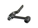 Toyota Idler Arm
 Toyota Power Steering Reservoir
 Toyota Steering Column Cover
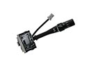 Toyota Windshield Wiper Switch
 Toyota Steering Angle Sensor
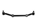 Toyota Center Link
 Toyota Power Steering Control Valve
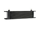 Toyota Power Steering Cooler
 Toyota Rack and Pinion Boot
 Toyota Tie Rod End
Browse Toyota Rack And Pinion by Models
Tacoma 4Runner Camry Tundra Corolla RAV4 Highlander Prius Sienna Land Cruiser Pickup FJ Cruiser 86 Sequoia T100 Avalon Celica Supra Yaris Matrix MR2 Solara Venza GR86 Echo C-HR Cressida Grand Highlander Paseo Previa Prius C Prius Prime bZ4X Corolla Cross Corolla iM Crown Crown Signia GR Corolla Mirai MR2 Spyder Prius V Starlet Tercel Van Yaris iA Prius Plug-In GR Supra Prius AWD-e RAV4 Prime