×
ToyotaParts- Hello
- Login or Register
- Quick Links
- Live Chat
- Track Order
- Parts Availability
- RMA
- Help Center
- Contact Us
- Shop for
- Toyota Parts
- Scion Parts
My Garage
My Account
Cart
OEM Toyota Echo Rack And Pinion
Steering Gear- Select Vehicle by Model
- Select Vehicle by VIN
Select Vehicle by Model
orMake
Model
Year
Select Vehicle by VIN
For the most accurate results, select vehicle by your VIN (Vehicle Identification Number).
6 Rack And Pinions found

Toyota Echo Steering Gear Part Number: 44200-52340
$610.09 MSRP: $894.08You Save: $283.99 (32%)Ships in 1-3 Business Days
Toyota Echo Steering Gear Part Number: 44250-52110
$634.05 MSRP: $928.99You Save: $294.94 (32%)Ships in 1-3 Business Days
Toyota Echo Gear Assembly Part Number: 44250-52200
$679.29 MSRP: $995.50You Save: $316.21 (32%)Ships in 1-3 Business Days
Toyota Echo Rack, Front Part Number: 44204-52010
$327.98 MSRP: $468.28You Save: $140.30 (30%)Ships in 1-3 Business Days
Toyota Echo Rack Part Number: 45521-52020
$88.08 MSRP: $123.64You Save: $35.56 (29%)Ships in 1-3 Business Days
Toyota Echo Steering Gear Part Number: 45510-52020
$687.80 MSRP: $1007.98You Save: $320.18 (32%)
Toyota Echo Rack And Pinion
Choose genuine Rack And Pinion that pass strict quality control tests. You can trust the top quality and lasting durability. Shopping for OEM Rack And Pinion for your Toyota Echo? Our website is your one-stop destination. We stock an extensive selection of genuine Toyota Echo parts. The price is affordable so you can save more. It only takes minutes to browse and find the exact fit. Easily add to cart and check out fast. Our hassle-free return policy will keep you stress-free. We process orders quickly for swift delivery. Your parts will arrive faster, so you can get back on the road sooner.
Toyota Echo Rack And Pinion Parts and Q&A
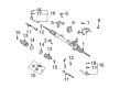
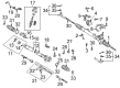
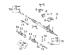
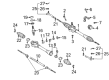
- Q: How to Service and Repair a Rack And Pinion System on Toyota Echo?A:Begin rack and pinion servicing and repair operations by taking it apart with a vise that should not be tightened excessively. The removal process for the 2 turn pressure tubes uses special service tool: 09633-00020 and requires removal of the 4 O-rings. Place the rack and pinion assembly in a vise utilizing special service tool: 09612-00012 right-hand before loosening both tie rod ends and rack ends so these components can be removed. The right-hand and left-hand clips and clamps along with rack boots must be carefully detached while marking components for identification before proceeding. Bind the right-hand rack end and use special service tool: 09922-10010 to detach the left-hand rack end before doing the same operation on the right-hand side. Special service tool: 09922-10010 can be used to remove the rack guide spring cap lock nut which allows extraction of rack guide spring cap, rack guide spring, rack guide spring spacer, and rack guide sub-assembly through a 19 mm hexagon wrench. The control valve housing and assembly can be separated by tracing positions before bolt removal followed by gentle extraction of the housing unit along with gasket removal. Set the control valve shaft with vinyl tape before using force to extract the control valve assembly while protecting the oil seal lip from damage. To remove the rack and pinion use special service tool: 09950-7001O (09951-07200) by eliminating the cylinder end stop through needle nose pliers while applying pressure on the rack and bushing. To extract the oil seal special service tool: 09950-60010 (09951-00240) must be used while maintaining the rack housing in good condition. The runout and teeth wear and damage conditions of the rack and pinion and bearing rotation and abnormal noise level require an inspection alongside potential control valve assembly replacement. Install the bearing alongside the oil seal by using special service tool: 09950-60010 (09951-00250), 09950-70010 (09951-07100). Also install both components correctly. Before installing the new O-ring into the rack and pinion it should be coated with power steering fluid and the rack teflon ring and O-ring components should be replaced while maintaining groove integrity. To replace the four rings from the control valve assembly keep the grooves intact while doing so. To install the new oil seal use special service tool: 09950-60010 (09951-00210, 09951-00370, 09952-06010) while properly operating it into the rack housing. The first step involves using the special service tool: 09631-10041 to fit the rack and pinion before installing a new O-ring that received power steering fluid coating on the bushing. Ensure the installation ensures that the oil seal lip remains damage-free. The cylinder end stopper requires push compression during snap ring installation. The air tightness must be tested with special service tool: 09631-12071 (09633-00010) to check vacuum stability levels. The teflon rings together with the oil seal lip require coating in power steering fluid before using special service tool: 09612-22011 to press the control valve assembly into the control valve housing. The process requires adding a new gasket while matching the marks exactly before bolting the control valve housing with 21 Nm (220 kgf.cm, 15 ft. lbs.) torque. Use sealant on rack guide spring cap threads before installing the rack guide sub-assembly, rack guide spring spacer and rack guide spring and rack guide spring cap in order. Install duplicate rack ends to adjust total preload before tightening the rack guide spring cap to 25 Nm (250 kgf.cm, 18 ft. lbs.) then return its position to 12 degrees. Special service tool: 09616-00010 must be used to turn the control valve shaft before loosening the rack guide spring cap using a torque span of 1.2 - 1.4 Nm (12 - 14 kgf.cm, 10.4 - 12.2 inch lbs.). The screw must be properly preloaded to reach its specified value. Apply sealant to the rack guide spring cap lock nut before torquing it to 28 Nm (290 kgf.cm, 21 ft. lbs.) using special service tool: 09922-10010 while reconfirming the total preload. Installation of the rack and pinion ends begins with right-hand followed by the left-hand ends until proper torque reaches 62 Nm (630 kgf.cm, 46 ft. lbs.). The right-hand and left-hand rack boots need to be installed after clamps and clips. The rack and pinion end hole must be kept clear. Add lock nuts to tie rod ends first before toe-in adjustment and subsequent locking of couplings to 47 Nm (480 kgf.cm, 35 ft. lbs.). Then install the 2 turn pressure tubes with new O-rings coated in power steering fluid and torque them to 10 Nm (100 kgf.cm, 7 ft. lbs.).
- Q: How to Remove and Install the Rack and Pinion in a Steering Gear System on Toyota Echo?A:A proper rack and pinion removal begins with aligning the wheels forward before you eliminate the Steering Wheel pad and the steering wheel. The first step involves disconnecting the RH and LH tie rod ends after removing the RH and LH engine under covers. Afterward, remove the No. 2 column hole cover. Dismiss the steering yoke alongside pressure and return tubes with Special Service Tool: 09023-12900 and separate the tube clamp via removing its retaining bolt. You should first take off the engine hood before using an engine sling device to hang the engine on hangers while installing the 2 No. 1 engine hangers (Parts No.: No. 1 engine hanger: 12281-21010, Bolt: 91511-60818) with a torque of 20 Nm (200 kgf-cm, 14 ft. lbs.). Disassemble the lower suspension arm from the steering knuckle and from the engine rear mount insulator and front suspension member by removing the bolt and then the 2 nuts. Use the transmission jack to support the combination of front suspension member with lower suspension arm and rack and pinion assembly before removing all 4 bolts that hold everything together. The procedure to remove the rack and pinion assembly starts with uninstalling the stabilizer bar followed by removing the bolt of the rack housing heat insulator and the 2 bolts and then taking out the rack housing heat insulator and dynamic damper and finally removing the column hole cover sub-assembly with its 4 bolts and nuts. Insert matchmarks onto the No. 3 intermediate shaft assembly and control valve shaft before unfastening the bolt and removing the No. 3 intermediate shaft assembly from the rack and pinion assembly. Also discard the bracket and grommet attached to the rack and pinion assembly. Start by using 3 bolts to install the engine rear mount bracket (torque: 49 Nm (500 kgf-cm, 36 ft. lbs.)) before fixing the engine rear mount insulator through its bolt and mounting the No. 2 engine rear mount bracket (torque: 64 Nm (650 kgf-cm, 47 ft. lbs.)). Static reference markings must be aligned between two components for the No. 3 intermediate shaft assembly and control valve shaft before installation of the bolt with a torque of 28 Nm (290 kgf-cm, 21 ft. lbs.) to join the assembly. Then install the bracket and grommet onto the rack and pinion assembly while ensuring that the front of the vehicle faces the designated inscribed mark. Position the rack and pinion assembly onto the front suspension member using 4 bolts and nuts that require torque to 74 Nm (750 kgf-cm, 54 ft. lbs.) and afterward add the column hole cover sub-assembly and dynamic damper with rack housing heat insulator secured through two bolts (torque: 18 Nm (180 kgf-cm, 13 ft. lbs.)) and the remaining installation involves the rack housing heat insulator bolt (torque: 35 Nm (360 kgf-cm, 26 ft. lbs.)). Reinstall the stabilizer bar after you align the holes of the front suspension member with the body using Special Service Tool: 09670-00010 to complete setup with lower suspension arm and rack and pinion assembly by tightening 4 bolts (Bolt A: 116 Nm (1,180 kgf-cm, 85 ft. lbs.), Bolt B: 70 Nm (715 kgf-cm, 52 ft. lbs.)). The procedure continues with the bolt securing the engine rear mount insulator to the front suspension member while using two nuts that require a torque of 80 Nm (810 kgf-cm, 59 ft. lbs.). Afterward, reinstall the lower suspension arm onto the steering knuckle and remove the engine sling device from the hangers of the engine. Attach the engine hood after which you should install pressure feed and return tubes temporarily then add the tube clamp with its bolt tightened to 7.8 Nm (80 kgf-cm, 69 inch lbs.). Use Special Service Tool: 09023-12900 to connect pressure feed and return tubes with a torque setting at 27 Nm (280 kgf-cm, 20 ft. lbs.) while connecting the return hose with the clip along with the column hole cover subassembly. After sliding yoke reinstallation connect the No. 2 column hole cover and proceed with attaching both RH and LH tie rod ends before installing the RH and LH engine under covers. Straighten the front wheels while centering the spiral cable until you can install the steering wheel matching the column main shaft marks prior to torquing the wheel set nut temporarily. Power steering bleeding procedures should follow while inspecting the steering wheel center point before torquing the steering wheel set nut to 50 Nm (510 kgf-cm, 37 ft. lbs.) for subsequent installation of the steering wheel pad as well as front wheel alignment verification.


Related Toyota Echo Parts
 Toyota Echo Power Steering Pump
 Toyota Echo Steering Wheel
 Toyota Echo Drag Link
 Toyota Echo Power Steering Control Valve
 Toyota Echo Power Steering Hose
 Toyota Echo Power Steering Reservoir
 Toyota Echo Rack and Pinion Boot
 Toyota Echo Steering Column
 Toyota Echo Steering Column Cover
 Toyota Echo Steering Gear Box
 Toyota Echo Steering Shaft
 Toyota Echo Tie Rod End