×
ToyotaParts- Hello
- Login or Register
- Quick Links
- Live Chat
- Track Order
- Parts Availability
- RMA
- Help Center
- Contact Us
- Shop for
- Toyota Parts
- Scion Parts
My Garage
My Account
Cart
OEM 2002 Toyota Echo Rack And Pinion
Steering Rack And Pinion- Select Vehicle by Model
- Select Vehicle by VIN
Select Vehicle by Model
orMake
Model
Year
Select Vehicle by VIN
For the most accurate results, select vehicle by your VIN (Vehicle Identification Number).
4 Rack And Pinions found

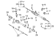
2002 Toyota Echo Rack
Part Number: 45521-52020$88.08 MSRP: $123.64You Save: $35.56 (29%)Ships in 1-3 Business DaysProduct Specifications- Other Name: Rack, Steering; Steering Gearbox; Steering Rack
- Part Name Code: 45521
- Item Weight: 5.60 Pounds
- Item Dimensions: 31.9 x 2.4 x 2.3 inches
- Condition: New
- Fitment Type: Direct Replacement
- SKU: 45521-52020
- Warranty: This genuine part is guaranteed by Toyota's factory warranty.

2002 Toyota Echo Rack, Front
Part Number: 44204-52010$327.98 MSRP: $468.28You Save: $140.30 (30%)Ships in 1-3 Business DaysProduct Specifications- Other Name: Rack Sub-Assembly, Power; Rack And Pinion Rack Gear, Front; Steering Gearbox; Steering Rack; Rack Sub-Assembly, Power Steering
- Position: Front
- Part Name Code: 44204
- Item Weight: 5.40 Pounds
- Item Dimensions: 32.7 x 3.2 x 2.8 inches
- Condition: New
- Fitment Type: Direct Replacement
- SKU: 44204-52010
- Warranty: This genuine part is guaranteed by Toyota's factory warranty.

2002 Toyota Echo Steering Gear
Part Number: 44250-52110$634.05 MSRP: $928.99You Save: $294.94 (32%)Ships in 1-3 Business DaysProduct Specifications- Other Name: Gear Assembly, Power Steering; Rack and Pinion Assembly; Steering Gearbox; Rack & Pinion; Gear Assembly; Gear Assembly, Power Steering(For Rack & Pinion)
- Replaces: 44200-52140
- Part Name Code: 44250
- Item Weight: 22.20 Pounds
- Item Dimensions: 41.0 x 13.0 x 7.1 inches
- Condition: New
- Fitment Type: Direct Replacement
- SKU: 44250-52110
- Warranty: This genuine part is guaranteed by Toyota's factory warranty.

2002 Toyota Echo Steering Gear
Part Number: 45510-52020$687.80 MSRP: $1007.98You Save: $320.18 (32%)Ships in 1-3 Business DaysProduct Specifications- Other Name: Gear Assembly, Steering; Rack and Pinion Assembly; Steering Gearbox; Gear Assembly
- Part Name Code: 45510
- Item Weight: 9.70 Pounds
- Item Dimensions: 49.7 x 10.5 x 6.6 inches
- Condition: New
- Fitment Type: Direct Replacement
- SKU: 45510-52020
- Warranty: This genuine part is guaranteed by Toyota's factory warranty.
2002 Toyota Echo Rack And Pinion
Looking for affordable OEM 2002 Toyota Echo Rack And Pinion? Explore our comprehensive catalogue of genuine 2002 Toyota Echo Rack And Pinion. All our parts are covered by the manufacturer's warranty. Plus, our straightforward return policy and speedy delivery service ensure an unparalleled shopping experience. We look forward to your visit!
2002 Toyota Echo Rack And Pinion Parts Q&A
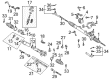
- Q: How to disassemble the Rack And Pinion on 2002 Toyota Echo?A: The rack and pinion disassembly process begins with the removal of 2 turn pressure tubes through Special Service Tool: 09023-38200 followed by extraction of the 4 O-rings. Install the Rack And Pinion assembly into a vise through Special Service Tool: 09612-00012. Before moving on mark both the tie rod end and rack end while you remove the tie rod end and lock nut from both sides. Use a screwdriver to loosen the clamp which enables the removal of the RH and LH clips together with clamps and rack boots. During removal avoid damaging the boots while you note their positions. Secure Special Service Tool: 09922-10010 to both ends of the RH rack and remove the LH rack with it, before proceeding with the RH rack removal. Use Special Service Tool: 09922-10010 to remove the rack guide spring cap lock nut followed by the rack guide spring cap and subsequently the rack guide spring and rack guide spring spacer and rack guide sub-assembly using a 19 mm hexagon wrench. The control valve assembly extraction requires the application of matchmarks and two bolt removal and draws it out with the installed gasket. To extract the end stopper of the cylinder first remove the snap ring followed by pulling it outwards. Use Special Service Tool: 09950-70010 (09951-07200) to press out the rack and pinion with the bushing and remove its O-ring from the space. Special Service Tool: 09950-60010 (09951-00240) should be used to press out the oil seal while maintaining safety of the rack housing. A dial indicator should be used to measure runout, teeth wear and damage on the rack and pinion. The maximum measurement should not exceed 0.1 mm (0.004 inch) and the needle roller bearing requires inspection for damage with potential rack housing replacement. When necessary replace the oil seal with Special Service Tool: 09612-24014 (09613-22011) while keeping the bushing undamaged then coat a new oil seal lip with power steering fluid before installing it with Special Service Tool: 09950-60010 (09951-00210, 09951-00340, 09952-06010), 09950-70010 (09951-07100). The old rack and pinion Teflon ring and O-ring must be removed before coating a new O-ring with power steering fluid before installation. You should install a new Teflon ring by expanding it first, applying power steering fluid on it, and placing it into the rack and pinion. The reassembly process requires power steering fluid coating of designated parts before installing the oil seal correctly positioned and in the intended direction. Follow this installation procedure by using Special Service Tool: 09631-10041 and coat it with power steering fluid before using the tool-free technique. Before installing the O-ring onto the bushing you need to soak it in power steering fluid then position it where the oil seal lip faces outward. Before application of the cylinder end stopper push it into position and install the snap ring. The vehicle needs an air tightness test performed using Special Service Tools: 09631-12071 (09633-00010) to apply 53 kPa (400 mmHg, 15.75 inch Hg) vacuum pressure for 30 seconds until no vacuum changes occur. Insert the control valve assembly by first installing its gasket then aligning the matchmarks before pushing it into place using 2 bolts secured to 21 Nm (220 kgf-cm, 15 ft. lbs.). Apply sealant to the threads of the cap before mounting the rack guide sub-assembly, rack guide spring spacer, rack guide spring and rack guide spring cap sequence. A total preload adjustment must be made by installing temporary RH and LH rack ends, torquing the rack guide spring cap to 25 Nm while returning it to 12 degrees. Hand tool 09616-00011 helps steer the control valve shaft while technicians should ease the rack guide spring cap open until it does not operate before tightening it to reach 1.2 - 1.4 Nm (12 - 14 kgf-cm) or (10.4 - 12.2 inch lbs.) of preload. Fix the rack guide spring cap lock nut with sealant before torquing it to 28 Nm using Special Service Tool: 09922-10010. Afterward, verify the total preload once more. To complete the task you should install the RH and LH rack ends and torque them to 62 Nm (630 kgf-cm, 46 ft. lbs.) while putting on the RH and LH rack boots, clamps, and clips before checking the rack and pinion end hole clearance with Special Service Tool: 09521-24010. The final step involves installing the 2-turn pressure tubes through Special Service Tool: 09023-38200 while torquing them to 11 Nm (110 kgf-cm, 8 ft. lbs.). Apply fresh power steering fluid to new O-rings before installing them.
Related 2002 Toyota Echo Parts
 2002 Toyota Echo Power Steering Pump
 2002 Toyota Echo Steering Wheel
 2002 Toyota Echo Drag Link
 2002 Toyota Echo Power Steering Control Valve
 2002 Toyota Echo Power Steering Hose
 2002 Toyota Echo Power Steering Reservoir
 2002 Toyota Echo Rack and Pinion Boot
 2002 Toyota Echo Steering Column Cover
 2002 Toyota Echo Steering Gear Box
 2002 Toyota Echo Steering Shaft
 2002 Toyota Echo Tie Rod End
 2002 Toyota Echo Wiper Switch