×
ToyotaParts- Hello
- Login or Register
- Quick Links
- Live Chat
- Track Order
- Parts Availability
- RMA
- Help Center
- Contact Us
- Shop for
- Toyota Parts
- Scion Parts
My Garage
My Account
Cart
OEM 2000 Toyota Echo Rack And Pinion
Steering Rack And Pinion- Select Vehicle by Model
- Select Vehicle by VIN
Select Vehicle by Model
orMake
Model
Year
Select Vehicle by VIN
For the most accurate results, select vehicle by your VIN (Vehicle Identification Number).
4 Rack And Pinions found

2000 Toyota Echo Rack
Part Number: 45521-52020$88.08 MSRP: $123.64You Save: $35.56 (29%)Ships in 1-3 Business DaysProduct Specifications- Other Name: Rack, Steering; Steering Gearbox; Steering Rack
- Part Name Code: 45521
- Item Weight: 5.60 Pounds
- Item Dimensions: 31.9 x 2.4 x 2.3 inches
- Condition: New
- Fitment Type: Direct Replacement
- SKU: 45521-52020
- Warranty: This genuine part is guaranteed by Toyota's factory warranty.

2000 Toyota Echo Rack, Front
Part Number: 44204-52010$327.98 MSRP: $468.28You Save: $140.30 (30%)Ships in 1-3 Business DaysProduct Specifications- Other Name: Rack Sub-Assembly, Power; Rack And Pinion Rack Gear, Front; Steering Gearbox; Steering Rack; Rack Sub-Assembly, Power Steering
- Position: Front
- Part Name Code: 44204
- Item Weight: 5.40 Pounds
- Item Dimensions: 32.7 x 3.2 x 2.8 inches
- Condition: New
- Fitment Type: Direct Replacement
- SKU: 44204-52010
- Warranty: This genuine part is guaranteed by Toyota's factory warranty.

2000 Toyota Echo Steering Gear
Part Number: 44250-52110$634.05 MSRP: $928.99You Save: $294.94 (32%)Ships in 1-3 Business DaysProduct Specifications- Other Name: Gear Assembly, Power Steering; Rack and Pinion Assembly; Steering Gearbox; Rack & Pinion; Gear Assembly; Gear Assembly, Power Steering(For Rack & Pinion)
- Replaces: 44200-52140
- Part Name Code: 44250
- Item Weight: 22.20 Pounds
- Item Dimensions: 41.0 x 13.0 x 7.1 inches
- Condition: New
- Fitment Type: Direct Replacement
- SKU: 44250-52110
- Warranty: This genuine part is guaranteed by Toyota's factory warranty.

2000 Toyota Echo Steering Gear
Part Number: 45510-52020$687.80 MSRP: $1007.98You Save: $320.18 (32%)Ships in 1-3 Business DaysProduct Specifications- Other Name: Gear Assembly, Steering; Rack and Pinion Assembly; Steering Gearbox; Gear Assembly
- Part Name Code: 45510
- Item Weight: 9.70 Pounds
- Item Dimensions: 49.7 x 10.5 x 6.6 inches
- Condition: New
- Fitment Type: Direct Replacement
- SKU: 45510-52020
- Warranty: This genuine part is guaranteed by Toyota's factory warranty.
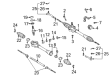
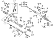
2000 Toyota Echo Rack And Pinion
Looking for affordable OEM 2000 Toyota Echo Rack And Pinion? Explore our comprehensive catalogue of genuine 2000 Toyota Echo Rack And Pinion. All our parts are covered by the manufacturer's warranty. Plus, our straightforward return policy and speedy delivery service ensure an unparalleled shopping experience. We look forward to your visit!
2000 Toyota Echo Rack And Pinion Parts Q&A
- Q: How to Service and Repair a Rack and Pinion Steering Gear on 2000 Toyota Echo?A: The manual rack and pinion assembly needs to be set in a vise using Special Service Tool: 09612-00012 but be cautious not to stretch the rack and pinion. Service the rack and pinion by first placing matchmarks on the tie rod ends then gently loosen the lock nuts to detach them with the right and left hands respectively. Liberate the right-hand and left-hand clips and clamps and rack boots by first loosening the clamp with pliers and then carefully extracting the clip and clamp with the boot intact while maintaining proper markings for both rack boots. First stabilize the rack while using Special Service Tool: 09922-10010 to unfasten the right-hand and left-hand rack ends. The rack guide spring cap lock nut should be removed first through Special Service Tool: 09922-10010 followed by successive removal of rack guide spring cap, rack guide spring spacer, conical spring washer, rack guide spring and rack guide sub-assembly. To eliminate the oil seal and spacer from the rack housing use a screwdriver covered with vinyl tape while carefully preventing damage to the housing before using snap ring pliers to detach the snap ring which lets you extract the pinion without harming serrations on its surface. Revolution of the rack must be avoided to prevent bushing damage when performing removal. A dial indicator helps check the rack for runout as well as teeth wear and damage by ensuring maximum runout stays below 0.15 mm (0.0059 inch). The inspection should also include examining the back surface for wear and damage. The indicated parts should receive a coating of molybdenum disulfide lithium base grease before installing the rack through the pinion side without rack revolution while setting its notched side toward the pinion. Position the pinion while pushing it forward then apply snap ring pliers to install the snap ring followed by the spacer and greased new oil seal before tapping it in using Special Service Tool: 09517-12010 and a hammer. The installation of rack guide sub-assembly along with rack guide spring and conical spring washer must be performed by placing the conical spring washer properly oriented while rack guide spring cap threads get sealant treatment before final installation. Temporarily install the rack guide spring cap. Users should do total preload manipulation by installing left-hand and right-hand rack ends. Then users must apply torque of 6.9 Nm (70 kgf.cm, 61 inch lbs.) to the rack guide spring cap while turning the pinion shaft and loosening the spring cap until it becomes nonfunctional before final tightened to a preload of 0.6 - 1.5 Nm (6 - 15 kgf.cm, 5.2 - 13.0 inch lbs.) through use of Special Service Tool: 09612-24014 (09616 The rack guide spring cap lock nut requires threads sealed with sealant before torquing it to 36 Nm (365 kgf.cm, 26 ft. lbs.) using Special Service Tool: 09922-10010 while rechecking the total preload. Utilize Special Service Tool: 09922-10010 for positioning each rack end before torquing it to 62 Nm (630 kgf.cm, 46 ft. lbs.). The next steps include attaching the rack boots and clamps along with their clips while avoiding boot damage or distortion, and finishing by fitting right-left tie rod ends and their lock nuts must be torqued to 47 Nm (480 kgf.cm, 35 ft. lbs.).
Related 2000 Toyota Echo Parts
 2000 Toyota Echo Power Steering Pump
 2000 Toyota Echo Steering Wheel
 2000 Toyota Echo Drag Link
 2000 Toyota Echo Power Steering Control Valve
 2000 Toyota Echo Power Steering Hose
 2000 Toyota Echo Power Steering Reservoir
 2000 Toyota Echo Rack and Pinion Boot
 2000 Toyota Echo Steering Column Cover
 2000 Toyota Echo Steering Gear Box
 2000 Toyota Echo Steering Shaft
 2000 Toyota Echo Tie Rod End
 2000 Toyota Echo Wiper Switch