My Garage
Cart
Make sure this part fits

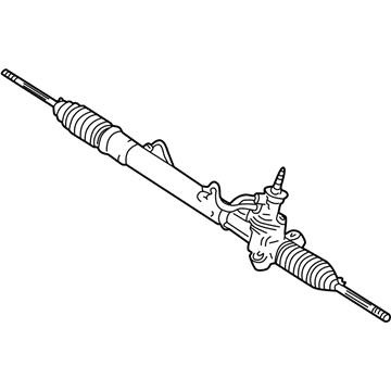
Toyota 44200-52340
Steering Gear

2003-2006 Toyota 4420052340

Customer Questions & Expert Answers (13)
Toyota 44200-52340 Steering Gear
  • Part Description
    Rack and Pinion Assembly; Steering Gearbox
  • Part Name Code
    44200
  • Manufacturer
    Toyota
Make sure this part fits
$610.09 MSRP: $894.08
You Save: $283.99 (32%)
Ships in 1-3 Business Days
1
ADD TO CART
  • Related Parts
  • Product Specifications
  • Vehicle Fitment
  • Customer Questions & Expert Answers
  • Product Specifications

    BrandGenuine Toyota
    Part Name Code44200
    Manufacturer Part Number44200-52340
    Part DescriptionRack and Pinion Assembly; Steering Gearbox
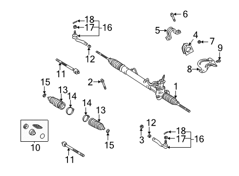
    Other NamesGear Assembly; Steering Gear Assembly; Link Assembly, Power Steering
    Item Dimensions50.2 x 10.4 x 6.6 inches
    Item Weight13.70 Pounds
    ConditionNew
    Fitment TypeDirect Replacement
    ManufacturerToyota
    SKU44200-52340
    WarrantyThis genuine Toyota part is guaranteed by Toyota's factory warranty.
    Shipping & ReturnShipping Policy Return Policy
    Warning: California's Proposition 65
  • Vehicle Fitment

    Year Make Model Trim Engine
    2004-2006 Scion xABase4 Cyl 1.5 L GAS
    2004-2006 Scion xBBase4 Cyl 1.5 L GAS
    2003-2005 Toyota EchoBase4 Cyl 1.5 L GAS
  • Customer Questions & Expert Answers

    Q:
    Will 44200-52340 fit my vehicle? Posted by ToyotaPartsNow Specialist
    A:
    Find out if part number 44200-52340 is the right fit for your car by Selecting Your Vehicle model.
    Posted by ToyotaPartsNow Specialist
    Q:
    How to Overhaul the Rack and Pinion in Power Steering Systems on Scion xA? Posted by Customer
    A:
    The first step to overhaul the POWER STEERING LINK ASSY involves using power steering fluid or molybdenum disulfide lithium base grease on specified areas. The service sequence begins with removing the FR WIPER ARM RH and LH, HOOD TO COWL TOP SEAL, COWL TOP VENTILATOR LOUVER RH and LH, WINDSHIELD WIPER MOTOR & LINK ASSY, and COWL PANEL SUB-ASSY. The COMBINED FRONT WHEEL area requires inspection before removing the STEERING COLUMN HOLE COVER PLATE. The steering wheel should stay fixed by seat belts to maintain stability during the separation process before placing matchmarks on both the sliding yoke sub-assy and intermediate shaft and loosening their bolt connection. Propagate clip A to detach the STEERING COLUMN HOLE COVER SUB-ASSY NO.1 without damaging clip B. Remove the HOOD SUB-ASSY and power steering fluid then remove FRONT WHEELS. Using Special Service Tools 09620-62011 and 09628-62011, remove the TIE ROD END SUB-ASSY LH and RH and then detach the ENGINE UNDER COVER LH and RH. Disconnection of the PRESSURE FEED TUBE ASSY requires removal of its clip while using Special Service Tool: 09023-12700. Use Special Service Tool 09628-00011 to separate the FRONT SUSPENSION ARM SUB-ASSY LOWER NO.1 on both the left-hand and right-hand sides. Two No.1 engine hangers (Parts No.: 12281-21010, 91642-81025) will be used for suspending the ENGINE ASSEMBLY. The workshop uses two No.1 engine hangers (part number 12281-21010 and bolt 91642-81025 fixed at 40 Nm) to suspend the engine assembly during FRONT SUSPENSION CROSSMEMBER SUB-ASSY removal. Move the POWER STEERING RACK HOUSING HEAT INSULATOR and STEERING COLUMN HOLE COVER SUB-ASSY NO.1 together with STEERING INTERMEDIATE SHAFT while noting original positions before disassembly. Remove the POWER STEERING RACK AND PINION following a marking procedure and removing its bolts, nuts, bracket No.2, grommet No.2, along with the assembly while torquing the bolt once nut is fixed. Use Service Tool 09023-38200 to remove the STEERING RIGHT TURN PRESSURE TUBE with its O-rings similar procedure occurs for the STEERING LEFT TURN PRESSURE TUBE. Set up Special Service Tool: 09612-00012 to fix and uninstall the POWER STEERING RACK AND PINION and thereafter loosen the TIE ROD END SUB-ASSY LH and RH lock nuts while retaining their positions. Cautiously detach the STEERING RACK BOOT CLIPS and clamps before taking off the STEERING RACK BOOT NO.2 and NO.1. Use Special Service Tool: 09922-10010 to remove the STEERING RACK END SUB-ASSY and proceed to remove the RACK GUIDE along with the POWER STEERING CONTROL VALVE by marking components positions then removing bolts. To proceed with the removal operation use Special Service Tool: 09950-70010 (09951-07200) and a press so you can eliminate the CYLINDER END STOPPER and POWER STEERING RACK followed by removing the POWER STEERING RACK BUSH and its oil seal. Take the RACK STEERING PISTON RING out carefully then measure POWER STEERING RACK behavior using a dial gauge to check both wear and runout. Check turning torque values of TIE ROD END SUB-ASSY LH and RH while placing them in a vise. Reinstall the POWER STEERING RACK HOUSING OIL SEAL yet use power steering fluid as a coating before adding the RACK STEERING PISTON RING in its correct position and with proper fluid application.
    Posted by ToyotaPartsNow Specialist
    Q:
    How to reassemble the Rack And Pinion on Scion xA? Posted by Customer
    A:
    A new power steering rack housing oil seal gets installed through a process that begins with power steering fluid lubricating the new oil seal lip followed by the use of Special Service Tool: 09950-60010 (09951-00210, 09951-00370, 09952-06010), 09950-70010 (09951-07360) and a press to correctly install the housing oil seal. You must start by placing power steering fluid on the O-Ring before adding it to the rack and pinion followed by stretching a fresh piston ring manually then applying more power steering fluid before finger-adjusting its installation on the rack. The installation of the rack and pinion requires Special Service Tool: 09631-10041 to guide this process while you apply power steering fluid onto the rack housing before removing the tool. Press the rack bush oil seal with a press while using Special Service Tool: 09950-60010 along with 09951-00210, 09951-00340, 09952-06010 and 09950-70010 and 09951-07100. After applying power steering fluid to the new O-ring users should wrap vinyl tape around the rack and pinion end before correctly installing the rack bush into the rack housing. First install the hole snap ring through the cylinder end stopper using needle nose pliers. Install Special Service Tool: 09631-12071 (09633-00010) onto the rack housing and apply a 53 kPa vacuum for 30 seconds to check air tightness. Any vacuum change indicates improper oil seal installation. Install the power steering control valve on the rack housing by first applying grease to the needle roller bearing. Then use new gasket and matchmarks to align the pieces before tightening the 2 bolts to 21 Nm (214 kgf-cm, 15 ft. lbs.). Part No. 08833-00080 THREE BOND 1344 LOCTITE 242 or equivalent sealant to 2 or 3 threads of the rack guide spring cap, install the cap temporarily. The adjustment process involves both rack ends while fastening the rack guide spring cap to 25 Nm (250 kgf-cm, 18 ft. lbs.) torque using a 19 mm hexagon wrench to return the cap approximately 12 degrees. Then using Special Service Tool: 09616-00011 to turn the control valve while loosening the cap until the spring stops functioning and finally tightening the cap to achieve total preload specification (1.2 to 1.5 Nm, 12 to 15 kgf-cm, 10.6 to 13.3 inch lbs.). Install and temporarily fix the spring cap lock nut after sealing 2 or 3 threads and use a 19 mm hexagon wrench to secure the rack guide spring cap followed by locking the spring cap nut at 28 Nm (286 kgf-cm, 21 ft. lbs.) utilized with Special Service Tool: 09922-10010 while using a torque wrench with 345 mm (13.58 inch) fulcrum length. Total preload should be rechecked before the removal of RH and LH rack ends. Secondarily position the rack ends before tightening them to 60 Nm (614 kgf-cm, 44 ft. lbs.) while using Special Service Tool: 09922-10010 correctly. The pressure inside the boot after assembly can be affected by a grease clog in the rack and pinion end hole so it needs to be inspected before final installation. Apply silicon grease to the inside small caliber of the No. 2 rack and pinion boot then position it inside the rack housing groove while avoiding damage or boot twisting. The procedures should be repeated for installing the No. 1 rack and pinion boot. Secure the No. 2 rack boot clamp using Special Service Tool: 09240-00020, 09521-24010 by attaining a standard clearance of 3.0 mm (0.118 inch) or less while avoiding boot damage. The identical boot clamp installation procedures must be performed on the No. 1 rack and pinion boot clamp. Fasten the rack and pinion boot clips by using pliers. The installation of the tie rod end sub-assembly LH includes screwing the lock nut and tie rod end onto the rack end until the matchmarks line up and torques to 74 Nm (750 kgf-cm, 54 ft. lbs.), then finally torquing the lock nut after adjusting toe-in. Apply the identical methods to install the tie rod end sub-assembly RH. Power steering fluid should be applied to 2 new O-rings which will be installed to the turn pressure tube along with the use of Special Service Tool: 09023-38201 to fix the tube to the rack and pinion through torqueing to 12 Nm (118 kgf-cm, 9 ft. lbs.) using a torque wrench with 250 mm (9.84 inch) fulcrum length and maintaining the tool parallel to the wrench. The same installation process should be followed for the rack and pinion turn pressure tube on the left-hand side (LH).
    Posted by ToyotaPartsNow Specialist
    Q:
    How to disassemble the Rack And Pinion on Scion xA? Posted by Customer
    A:
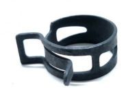
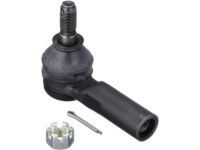
    Before removing the power steering link you must secure the steering link assembly using Special Service Tool: 09612-00012 and wrap it with vinyl tape beforehand. Begin by marking the tie rod end LH and rack end and proceed to loose the lock nut to extract the tie rod end and lock nut. Apply the same approach to remove the tie rod end on the right-hand side. The first step for boot removal involves taking out both rack and pinion boot clips followed by using a screwdriver to carefully separate the No. 2 rack and pinion boot clamp. Prevent damage to the boot while performing this step. First remove the boot clamp located at No. 1 then continue with the No. 2 and No. 1 rack and pinion boots' removal. The collection of Special Service Tool: 09922-10010 permits removal of the two rack ends before using the same tool to remove the spring cap lock nut so technicians can finish the procedure by using a 19 mm hexagon wrench to separate the rack guide spring cap. The technician needs to remove the rack guide spring followed by the rack guide spring spacer and the rack guide. The procedure for replacing the power steering control valve starts with marking the control valve and rack housing followed by bolt removal and extraction of the gasket together with the control valve and bolts. The needle nose pliers remove the hole snap ring to expose the cylinder end stopper which can then be pulled out. Special Service Tool: 09950-70010 (09951-07200) together with a press enable you to eliminate the power steering rack and rack bush from the system. Steer the rack bush from the rack and pinion and then employ Special Service Tool: 09612-24014 (09613-22011) to extract the rack bush oil seal followed by O-ring removal with a screwdriver. When replacing the rack and pinion piston ring you need to use a screwdriver to unfasten the ring and its accompanying O-ring without harming the ring grooves. Use Special Service Tool: 09950-60010 (09951-00200, 09951-00240, 09952-06010) and 09950-70010 (09951-07360) along with a press to remove the housing oil seal from the rack housing cautiously. A dial gauge should measure the power steering rack for runout, teeth wear and damage; replace the rack if the maximum deviation exceeds 0.1 mm (0.004 inch). Insert the tie rod end assembly into a vise then attach the nut to the stud bolt before moving the ball joint stud five times one after another and apply the torque wrench to continuously rotate the nut over 2 to 4 seconds each time to record the reading on turn five with a standard torque range from 0.8 Nm to 3.4 Nm (8.2 to 34.7 kgf-cm, 7.1 to 30.1 inch lbs.).
    Posted by ToyotaPartsNow Specialist
    Q:
    How do you install the steering link assembly for the 2005 Scion xA? Posted by Customer
    A:
    Apply power steering fluid to the 2 new O-rings and install them to the right turn pressure tube, then install the tube to the steering link assembly using Special Service Tool: 09023-38201, torquing to 12 Nm (118 kgf-cm, 9 ft. lbs.). Repeat for the left turn pressure tube.
    Posted by ToyotaPartsNow Specialist
    See expert answers on similar Rack And Pinion
    Q:
    How do you remove the right and left turn pressure tubes for the 2005 Scion xB? Posted by Customer
    A:
    Use Special Service Tool: 09023-38201 and secure the power steering link assembly with Special Service Tool: 09612-00012.
    Posted by ToyotaPartsNow Specialist
    See expert answers on similar Rack And Pinion
    Q:
    What final checks should be performed before completing the installation for the 2006 Scion xB? Posted by Customer
    A:
    Check fluid levels, bleed the system, and inspect for leaks before completing the installation of the hood and other exterior components.
    Posted by ToyotaPartsNow Specialist
    See expert answers on similar Rack And Pinion
    Q:
    What inspection is required before proceeding for the 2006 Scion xA? Posted by Customer
    A:
    Inspect the center front wheel.
    Posted by ToyotaPartsNow Specialist
    See expert answers on similar Rack And Pinion
    Q:
    What is the procedure for installing the rack ends for the 2004 Scion xA? Posted by Customer
    A:
    Remove the RH and LH rack ends sub-assy, temporarily install the 2 rack end sub-assy, and torque them to 60 Nm (614 kgf-cm, 44 ft. lbs.) using Special Service Tool: 09922-10010.
    Posted by ToyotaPartsNow Specialist
    See expert answers on similar Rack And Pinion
    Q:
    What is the procedure for the air tightness test for the 2004 Scion xB? Posted by Customer
    A:
    Install Special Service Tool: 09631-12071 (09633-00010) onto the rack housing, apply a vacuum of 53 kPa (400 mm Hg, 15.75 inch Hg) for approximately 30 seconds, and check for any change in the vacuum, addressing any issues with the oil seals if necessary.
    Posted by ToyotaPartsNow Specialist
    See expert answers on similar Rack And Pinion
    Q:
    How should the front suspension member be supported for the 2003 Toyota Echo? Posted by Customer
    A:
    Support it with the lower suspension arm using a transmission jack.
    Posted by ToyotaPartsNow Specialist
    See expert answers on similar Rack And Pinion
    Q:
    What should be done after removing the rack guide spring cap lock nut for the 2004 Toyota Echo? Posted by Customer
    A:
    Use a hexagon wrench (19 mm) to take off the rack guide spring cap, followed by the rack guide spring, rack guide spring spacer, and rack guide sub-assembly.
    Posted by ToyotaPartsNow Specialist
    See expert answers on similar Rack And Pinion
    Q:
    What is the process to press out the steering rack for the 2005 Toyota Echo? Posted by Customer
    A:
    Press out the steering rack with the bushing using SST 09950-70010 (09951-07200) and remove the O-ring from the bushing.
    Posted by ToyotaPartsNow Specialist
    See expert answers on similar Rack And Pinion
    If you have any questions about this product, please don't hesitate to ask us. We will be happy to help you!

OEM Toyota 44200-52340, Excellent Performance and Perfect Fitment

To ensure reliability, purchase Toyota part # 44200-52340 Steering Gear. It is sometimes referred to as Toyota Rack And Pinion. OEM parts are unrivaled in terms of quality. They go through extensive quality control inspections and are produced in accordance with Toyota's official factory specifications. All of these remove defects and imperfections. So you can relax knowing they promise exceptional lifespan and flawless fitment.

ToyotaPartsNow.com is a leading supplier of genuine Toyota parts such as Toyota 4420052340 Steering Gear. At ToyotaPartsNow.com, we have a wide variety of OEM Toyota parts available at competitive prices. Our comprehensive range of genuine Toyota parts come with a manufacturer's warranty for peace of mind. We also prioritize customer satisfaction, providing a hassle-free return policy and expedited delivery for all our parts. For detailed Toyota parts information, click here.
Choose ToyotaPartsNow for discounted prices, exceptional service and fast delivery