×
ToyotaParts- Hello
- Login or Register
- Quick Links
- Live Chat
- Track Order
- Parts Availability
- RMA
- Help Center
- Contact Us
- Shop for
- Toyota Parts
- Scion Parts
My Garage
My Account
Cart
OEM Toyota 4Runner Rack And Pinion
Steering Gear- Select Vehicle by Model
- Select Vehicle by VIN
Select Vehicle by Model
orMake
Model
Year
Select Vehicle by VIN
For the most accurate results, select vehicle by your VIN (Vehicle Identification Number).
10 Rack And Pinions found


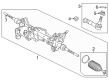
Toyota 4Runner Steering Gear Part Number: 44250-35042
$547.17 MSRP: $801.89You Save: $254.72 (32%)Ships in 1-3 Business Days

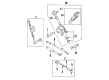
Toyota 4Runner Link Assembly, Power Steering Part Number: 44200-35061
$653.07 MSRP: $957.08You Save: $304.01 (32%)Ships in 1-3 Business Days

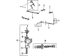
Toyota 4Runner Steering Gear Part Number: 44200-35094
$773.15 MSRP: $1133.06You Save: $359.91 (32%)Ships in 1-2 Business Days
Toyota 4Runner Steering Gear Part Number: 44200-35070
$976.36 MSRP: $1430.87You Save: $454.51 (32%)Ships in 1-2 Business Days


Toyota 4Runner Steering Gear Part Number: 45310-35330
$1213.98 MSRP: $1779.11You Save: $565.13 (32%)Ships in 1-3 Business Days
Toyota 4Runner Rack, Front Part Number: 44204-35050
$416.99 MSRP: $611.10You Save: $194.11 (32%)Ships in 1-3 Business Days
Toyota 4Runner Gear Assembly, Electric Part Number: 44250-35120
$953.84 MSRP: $1397.87You Save: $444.03 (32%)Ships in 1-2 Business Days
Toyota 4Runner Steering Gear Part Number: 44110-35360
$3749.94 MSRP: $5495.57You Save: $1745.63 (32%)Ships in 1-3 Business Days
Toyota 4Runner Rack, Front Part Number: 44204-35020

Toyota 4Runner Steering Gear Part Number: 44110-35032
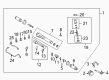
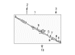
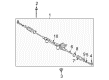
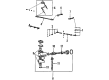
Toyota 4Runner Rack And Pinion
Choose genuine Rack And Pinion that pass strict quality control tests. You can trust the top quality and lasting durability. Shopping for OEM Rack And Pinion for your Toyota 4Runner? Our website is your one-stop destination. We stock an extensive selection of genuine Toyota 4Runner parts. The price is affordable so you can save more. It only takes minutes to browse and find the exact fit. Easily add to cart and check out fast. Our hassle-free return policy will keep you stress-free. We process orders quickly for swift delivery. Your parts will arrive faster, so you can get back on the road sooner.
Toyota 4Runner Rack And Pinion Parts and Q&A
- Q: How to disassemble the Rack And Pinion on Toyota 4Runner?A:Initiate rack and pinion disassembly by eliminating the turn pressure tubes with SST 09023-38200 and extracting four union seats from both rack housing and control valve housing. Position the Rack And Pinion assembly into a SST 09612-00012 vise while securing by means of bolts 90105-10346 and nuts 90170-10198. Before you loosen and extract the components mark the locking fasteners on the tie rod ends and rack ends. Ease the removal of the clips along with rack boots and clamps using cautious techniques to protect the boot components while marking their placement order. Use a screwdriver and hammer to unstake the claw washers while checking for any damage to the rack and pinion. Afterward, grasp the rack and pinion with a spanner to uninstall the rack ends by using SST 09922-10010. The maintenance procedure starts with the removal of the rack guide spring cap lock nut and the rack guide spring cap after which you proceed to remove the rack guide spring and dust cover. First mark the alignment of the control valve housing then remove its bolts to extract the assembly with the O-ring. Remove the O-ring after using SST 09631-20060 to ease the bearing guide nut and tapping out the control valve assembly. SST 09950-70010 (09951-07360) and SST 09922-10010 help in the removal of the rack and pinion and oil seal and the end stopper of the cylinder. A thorough examination of the rack and pinion should include measurements of runout and wear assessment while checking for needle roller bearing damage which may require application of molybdenum disulfide lithium base grease. Installation of new oil seal and bearing must be performed with SST 09950-60010 (09951-00260) in the proper direction. Inspection for cracks of this bushing must be conducted before applying grease during necessary replacement. Install new union seats through using a screw extractor followed by their assembly with a plastic hammer. The correct orientation for oil seal replacement requires the use of SST 09950-60010 (09951-00320). Change all Teflon rings and O-rings of the rack and pinion but take time to lubricate them with power steering fluid before assembling them into place. When assembling the parts soak them in power steering fluid or grease before using SST 09951-60010 (09951-00330) to install the oil seal and spacer and then install the rack and pinion. Affix SST 09922-10010 on the cylinder end stopper before applying correct torque while testing the air tightness with SST 09631-12071. The control valve assembly installation requires lubricated Teflon rings with subsequent bearing guide nut attachment through SST 09631-20060. The procedure starts with the installation of control valve housing which needs to be followed by installation of dust cover and rack guide and rack guide spring cap while applying specified sealant. Adjust the total preload of the rack guide spring cap while installing its lock nut with specified sealant then double-check the preload measurement. Begin by tightening the claw washers and rack ends before adding rack boots and clips which must be free from tube hole blockage and place 2 turn pressure tubes with new union seats at the end of the installation process.
- Q: How to install the Rack And Pinion and complete the associated procedures on Toyota 4Runner?A:The installation requires a torque of 100 Nm (1,020 kgf-cm, 74 ft-lbf) on 2 bolts and 2 nuts of the power steering link assembly while manually turning the bolt due to its detent. Secure the stabilizer bar front by stabilizing the suspension and connect the rack and pinion outlet return tube through the use of a union nut wrench which requires 42 Nm (428 kgf-cm, 31 ft-lbf) torque while maintaining a torque wrench with 300 mm (11.81 in.) fulcrum length and parallel to the Special Service Tool. The procedure requires installation of the hose with clip followed by mounting the pressure feed tube assembly onto the frame sub-assembly using two bolts tightened to 28 Nm (286 kgf-cm, 21 ft-lbf) then secure the flare nut with a union nut wrench to 42 Nm (428 kgf-cm, 31 ft-lbf) under equivalent torque wrench conditions. Fasten the steering intermediate shaft sub-assembly No. 2 before connecting the tie rod end sub-assembly LH to the steering knuckle arm by applying a 91 Nm (928 kgf-cm, 67 ft-lbf) torque force that will be fastened using a nut and cotter pin. Apply the identical procedure to tighten the RH components. The installation starts with under cover sub-assembly No.1 using four bolts and proceeds to install the rear engine under cover assembly using six bolts and concludes with front wheel installation at 110 Nm (1,122 kgf-cm, 81 ft-lbf) torque. First aim both front wheels to remain straight followed by attachments of the Turn Signal Switch assembly and spiral cable as well as the steering column cover lower and centering the spiral cable. Attache the Steering Wheel assembly before verifying the steering wheel center point and installing the steering pad while inspecting it for any fault. Also check the SRS warning light. The service needs power steering fluid addition along with power steering fluid bleeding procedure and a test for power steering fluid leaks. Front wheel alignment needs both an inspection and adjustment process as the final step.


Related Toyota 4Runner Parts
 Toyota 4Runner Power Steering Pump
 Toyota 4Runner Steering Angle Sensor
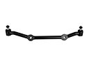 Toyota 4Runner Center Link
 Toyota 4Runner Drag Link
 Toyota 4Runner Fuel Line Clamps
 Toyota 4Runner Power Steering Cooler
 Toyota 4Runner Power Steering Hose
 Toyota 4Runner Rack and Pinion Boot
 Toyota 4Runner Shift Interlock Solenoid
 Toyota 4Runner Tie Rod End
 Toyota 4Runner Timing Belt Idler Pulley
 Toyota 4Runner Turn Signal Switch