×
ToyotaParts- Hello
- Login or Register
- Quick Links
- Live Chat
- Track Order
- Parts Availability
- RMA
- Help Center
- Contact Us
- Shop for
- Toyota Parts
- Scion Parts
My Garage
My Account
Cart
OEM 2002 Toyota 4Runner Rack And Pinion
Steering Rack And Pinion- Select Vehicle by Model
- Select Vehicle by VIN
Select Vehicle by Model
orMake
Model
Year
Select Vehicle by VIN
For the most accurate results, select vehicle by your VIN (Vehicle Identification Number).
2 Rack And Pinions found


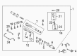
2002 Toyota 4Runner Steering Gear
Part Number: 44250-35042$547.17 MSRP: $801.89You Save: $254.72 (32%)Ships in 1-3 Business DaysProduct Specifications- Other Name: Gear Assembly, Power Steering; Rack and Pinion Assembly; Steering Gearbox; Gear Assembly; Gear Assembly, Power Steering(For Rack & Pinion)
- Replaces: 44250-35041, 44250-35040
- Part Name Code: 44250
- Item Weight: 28.30 Pounds
- Item Dimensions: 39.5 x 7.4 x 10.6 inches
- Condition: New
- Fitment Type: Direct Replacement
- SKU: 44250-35042
- Warranty: This genuine part is guaranteed by Toyota's factory warranty.

2002 Toyota 4Runner Rack, Front
Part Number: 44204-35050$404.84 MSRP: $593.30You Save: $188.46 (32%)Ships in 1-3 Business DaysProduct Specifications- Other Name: Rack Sub-Assembly, Power; Rack And Pinion Rack Gear, Front; Steering Gearbox; Steering Rack; Rack Sub-Assembly, Power Steering
- Position: Front
- Part Name Code: 44204
- Item Weight: 5.50 Pounds
- Item Dimensions: 32.1 x 3.2 x 2.8 inches
- Condition: New
- Fitment Type: Direct Replacement
- SKU: 44204-35050
- Warranty: This genuine part is guaranteed by Toyota's factory warranty.
2002 Toyota 4Runner Rack And Pinion
Looking for affordable OEM 2002 Toyota 4Runner Rack And Pinion? Explore our comprehensive catalogue of genuine 2002 Toyota 4Runner Rack And Pinion. All our parts are covered by the manufacturer's warranty. Plus, our straightforward return policy and speedy delivery service ensure an unparalleled shopping experience. We look forward to your visit!
2002 Toyota 4Runner Rack And Pinion Parts Q&A
- Q: How to remove and install the Rack And Pinion on 2002 Toyota 4Runner?A: Rack and pinion removal begins by ensuring front wheels point directly ahead and then moving forward by removing the steering wheel pad and steering wheel. First remove the engine under cover with its 10 bolts and then the stabilizer bar before disconnecting both right-hand and left-hand tie rod ends. The technician must cut intermediate shaft No. 2 from the pressure feed and return tubes using Special Service Tool 09023-38400. The power rack and pinion assembly removal process begins by unfastening the bracket bolt and nut before removing the two set bolts and the rack and pinion assembly together with its washer and nut component. Complete this job by first removing the bracket then removing the grommet. Start the installation by attaching first the grommet and bracket before positioning the rack and pinion assembly while torquing the assembly set bolt to 165 Nm (1,700 kgf-cm, 123 ft. lbs.) and the assembly set bolt, nut, and washer to 130 Nm (1,330 kgf-cm, 96 ft. lbs.) and finally the bolt and nut to the bracket at 165 Nm (1,700 kgf-cm, 123 ft. lbs.). Connect the pressure feed and return tubes through Special Service Tool: 09023-38400 while torquing pressure feed tubes to 41 Nm (420 kgf-cm, 30 ft. lbs.) and return tubes to 45 Nm (460 kgf-cm, 33 ft. lbs.). Establish the connection between intermediate shaft No. 2 and right-hand and left-hand tie rod ends and stabilize the system through the bar installation. Set the front wheel to face directly forward and maintain it in a raised position through axle support before aligning the spiral cable in its center. Insert the wheel into position according to matchmarks of the wheel and steering column main shaft then tighten the wheel set nut temporarily before joining the connector. The mechanic must bleed the power steering system followed by steering wheel center point inspection then tighten the steering wheel set nut to 50 Nm (510 kgf-cm, 37 ft. lbs.). As a final step install the steering wheel pad then check the front wheel alignment before using ten bolts to bolt down the engine under cover while torquing them to 30 Nm (300 kgf-cm, 22 ft. lbs.).
Related 2002 Toyota 4Runner Parts
 2002 Toyota 4Runner Steering Wheel
 2002 Toyota 4Runner Steering Shaft
 2002 Toyota 4Runner Drag Link
 2002 Toyota 4Runner Power Steering Control Valve
 2002 Toyota 4Runner Power Steering Reservoir
 2002 Toyota 4Runner Rack and Pinion Boot
 2002 Toyota 4Runner Steering Column
 2002 Toyota 4Runner Steering Column Cover
 2002 Toyota 4Runner Steering Gear Box
 2002 Toyota 4Runner Tie Rod End
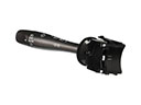 2002 Toyota 4Runner Turn Signal Switch
 2002 Toyota 4Runner Wiper Switch