- Hello
- Login or Register
- Quick Links
- Live Chat
- Track Order
- Parts Availability
- RMA
- Help Center
- Contact Us
- Shop for
- Toyota Parts
- Scion Parts

Popular OEM Toyota 4Runner Parts
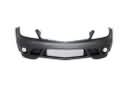
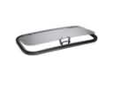
- Body & Hardware Parts View More >
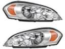
- Electrical Parts View More >
- Engine Parts View More >
- Air & Fuel Delivery Parts View More >
- Belts & Cooling Parts View More >
- Steering Parts View More >
- Suspension Parts View More >
- Emission Control & Exhaust Parts View More >
- A/C & Heating Parts View More >
- Charging & Starting Parts View More >
- Brakes Parts View More >
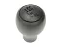
- Transmission Parts View More >


Why Buy Genuine Toyota 4Runner Parts From ToyotaPartsNow.com
ToyotaPartsNow.com highlights the reliability of OEM Toyota 4Runner parts right at your fingertips. Our skilled staff assists customers in selecting the right Toyota 4Runner parts and provides expert help with any unique part requests. At ToyotaPartsNow.com, we make all Toyota 4Runner parts available to you quickly and efficiently through our fast order and reliable ship process. Our service is designed to make finding the correct Toyota 4Runner parts fast and easy whether you are an amateur or a professional. We offer access to a broad inventory that includes a wide range of Toyota years and variants. Affordable prices, quick processing and professional service are also our specialty to ensure your car remains in top condition with OEM Toyota 4Runner parts. You can feel confident shopping with us because all Toyota 4Runner parts, such as Driveline & Axles you purchase from our store are of genuine quality and built to last.
Since its original release in 1984 the Toyota 4Runner received updates which preserved the basic SUV construction principles. The Hilux Surf model appeared in Japan in 1984 but Toyota renamed it the Toyota 4Runner after implementing multiple powertrain and technological advancements throughout its production period. A chain-driven transmission combined with a transfer case system was integrated into the 1988 model of Toyota 4Runner to create a quieter cabin experience compared to the rack-and-pinion gearbox in prior models. The vehicle with V6 engine included an advanced rear differential system which enhanced both its off-road capabilities and performance quality. The 1989 release of the 4Runner brought bigger dimensions and stretched wheelbase which created more seat space for passengers to enhance their comfort. Modular headlamps and one-piece bumpers became standard equipment on the Toyota 4Runner when the vehicle introduced its design in the early 1990s separate from the Hilux chassis platform. The third-generation Toyota 4Runner received enhanced performance characteristics when its new generation Tacoma engines were integrated. The Toyota Tahara plant maintained sole responsibility for building Toyota 4Runners that supplied uniform product excellence between all production models. The manufacturer provides exact parts assembled by Toyota for 4Runner maintenance because they satisfy factory requirements with warranty protection ensuring durability.
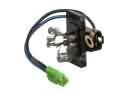
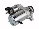
Toyota 4Runner owners often face mechanical issues with key parts. Many of the issues can be prevented through regular maintenance. Hesitation or failure to shift occurs in Toyota 4Runner automatic transmission at around 125,000 to 150,000 miles. This problem is often the result of a throttle position sensor that is out of range, or a sticking shift solenoid. Replacing the Toyota 4Runner throttle position sensor or even changing the solenoid has also been seen to restore smooth shifting without having to replace the transmission. Another headache comes in the flicking on of the Toyota 4Runner Check Engine light. It often due to clogged vapors or a fractured charcoal canister in the EVAP system. Replacing the purge solenoid and canister clears the code and removes the fuel smell. The last big concern is the Toyota 4Runner's silent starter. When the solenoid contacts in the starter get corroded, there can be no power flow, thus leaving the engine very silent. Fitting a low-cost contact kit brings about strong cranking power that make replacement of the complete starter unnecessary. Such quick solutions ensure that the power, fuel economy and resale value of the Toyota 4Runner remain protected. Short test drives, visual inspections and regular fluid changes help find problems early. Regular maintenance and timely repairs are essential for keeping these systems functioning optimally.
Toyota 4Runner Parts and Q&A
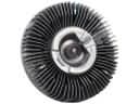
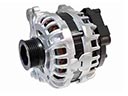
- Q: How to remove the alternator on Toyota 4Runner?A:To remove the alternator, disconnect the battery negative terminal, then remove 11 clips, the radiator upper support seal, and the fan and generator V belt. Detach the fan and fluid coupling, then remove the vane pump assembly. Finally, disconnect the generator connector and remove the generator assembly.
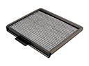
- Q: How to service and repair the cabin air filter on Toyota 4Runner?A:To service the cabin air filter, start by releasing the two claw fittings to detach the air filter sub-assembly. Then, remove the air refiner element from the air filter cover plate.
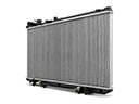
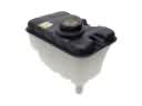
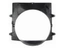
- Q: How to install the radiator assembly and its components on Toyota 4Runner?A:Installation of radiator assembly requires the use of support tabs with insertion in service holes and tightening with 4 bolts at 18 Nm. Install the fan shroud (5.0 Nm) with 2 bolts, the reserve tank (5.0 Nm) with 3 bolts, the hose, the coolant, and look after the leaks.


