×
ToyotaParts- Hello
- Login or Register
- Quick Links
- Live Chat
- Track Order
- Parts Availability
- RMA
- Help Center
- Contact Us
- Shop for
- Toyota Parts
- Scion Parts
My Garage
My Account
Cart
OEM 2009 Toyota 4Runner Rack And Pinion
Steering Rack And Pinion- Select Vehicle by Model
- Select Vehicle by VIN
Select Vehicle by Model
orMake
Model
Year
Select Vehicle by VIN
For the most accurate results, select vehicle by your VIN (Vehicle Identification Number).
1 Rack And Pinion found


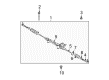
2009 Toyota 4Runner Steering Gear
Part Number: 44200-35070$976.36 MSRP: $1430.87You Save: $454.51 (32%)Ships in 1-2 Business DaysProduct Specifications- Other Name: Link Assembly, Power Steering; Rack and Pinion Assembly; Steering Gearbox; Gear Assembly
- Part Name Code: 44200
- Item Weight: 49.50 Pounds
- Item Dimensions: 52.7 x 11.1 x 6.9 inches
- Condition: New
- Fitment Type: Direct Replacement
- SKU: 44200-35070
- Warranty: This genuine part is guaranteed by Toyota's factory warranty.
2009 Toyota 4Runner Rack And Pinion
Looking for affordable OEM 2009 Toyota 4Runner Rack And Pinion? Explore our comprehensive catalogue of genuine 2009 Toyota 4Runner Rack And Pinion. All our parts are covered by the manufacturer's warranty. Plus, our straightforward return policy and speedy delivery service ensure an unparalleled shopping experience. We look forward to your visit!
2009 Toyota 4Runner Rack And Pinion Parts Q&A
- Q: How to remove and replace the Rack And Pinion on 2009 Toyota 4Runner?A: The power steering link assembly needs installation using two bolts and two nuts with 100 Nm (1,020 kgf-cm, 74 ft-lbf) torque applied during bolt rotation instead of the nut rotation. Place the rack and pinion outlet return tube with a union nut wrench while applying a torque of 40 Nm (407 kgf-cm, 29 ft-lbf), use a torque wrench with a 300 mm (11.81 in.) fulcrum length for measurement precision. The pressure feed tube assembly must be positioned on the frame sub-assembly through two bolts which require a torque of 28 Nm (286 kgf-cm, 21 ft-lbf) before tightening the flare nut with a union nut wrench at 40 Nm (407 kgf-cm, 29 ft-lbf). The rack and pinion intermediate shaft sub-assembly No. 2 requires tightening before attachment of the tie rod end sub-assembly LH to the steering knuckle arm using a nut and cotter pin at 91 Nm (928 kgf-cm, 67 ft-lbf). The assembly process requires engine under cover sub-assembly No. 1 with 4 bolts and rear engine under cover assembly with 6 bolts. Mount the front wheels in their positions while applying a torque of 110 Nm (1,122 kgf-cm, 81 ft-lbf) and set them in a straight-ahead direction. After installing the turn signal switch assembly mount the spiral cable with the steering column cover lower followed by spiral cable centering and steering wheel assembly placement. First inspect the steering wheel center point and install the steering pad and examine both components together with the SRS warning light. The mechanic will add power steering fluid followed by power steering fluid bleeding procedures and lastly inspect for any signs of leakage. You should execute front wheel alignment inspection as well as necessary adjustments at the end.
Related 2009 Toyota 4Runner Parts
 2009 Toyota 4Runner Steering Wheel
 2009 Toyota 4Runner Power Steering Pump
 2009 Toyota 4Runner Steering Shaft
 2009 Toyota 4Runner Drag Link
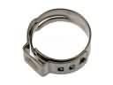 2009 Toyota 4Runner Fuel Line Clamps
 2009 Toyota 4Runner Power Steering Reservoir
 2009 Toyota 4Runner Rack and Pinion Boot
 2009 Toyota 4Runner Steering Column
 2009 Toyota 4Runner Steering Column Cover
 2009 Toyota 4Runner Tie Rod End
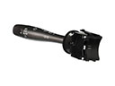 2009 Toyota 4Runner Turn Signal Switch
 2009 Toyota 4Runner Wiper Switch