×
ToyotaParts- Hello
- Login or Register
- Quick Links
- Live Chat
- Track Order
- Parts Availability
- RMA
- Help Center
- Contact Us
- Shop for
- Toyota Parts
- Scion Parts
My Garage
My Account
Cart
OEM 2008 Toyota 4Runner Rack And Pinion
Steering Rack And Pinion- Select Vehicle by Model
- Select Vehicle by VIN
Select Vehicle by Model
orMake
Model
Year
Select Vehicle by VIN
For the most accurate results, select vehicle by your VIN (Vehicle Identification Number).
1 Rack And Pinion found


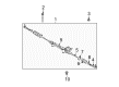
2008 Toyota 4Runner Steering Gear
Part Number: 44200-35070$976.36 MSRP: $1430.87You Save: $454.51 (32%)Ships in 1-2 Business DaysProduct Specifications- Other Name: Link Assembly, Power Steering; Rack and Pinion Assembly; Steering Gearbox; Gear Assembly
- Part Name Code: 44200
- Item Weight: 49.50 Pounds
- Item Dimensions: 52.7 x 11.1 x 6.9 inches
- Condition: New
- Fitment Type: Direct Replacement
- SKU: 44200-35070
- Warranty: This genuine part is guaranteed by Toyota's factory warranty.
2008 Toyota 4Runner Rack And Pinion
Looking for affordable OEM 2008 Toyota 4Runner Rack And Pinion? Explore our comprehensive catalogue of genuine 2008 Toyota 4Runner Rack And Pinion. All our parts are covered by the manufacturer's warranty. Plus, our straightforward return policy and speedy delivery service ensure an unparalleled shopping experience. We look forward to your visit!
2008 Toyota 4Runner Rack And Pinion Parts Q&A
- Q: How to reassemble the Rack And Pinion on 2008 Toyota 4Runner?A: The reassembly process of power steering link begins with rack and pinion piston ring installation followed by O-ring coating with power steering fluid before rack placement. After that expand and moisten a new Teflon ring before settling it onto the rack. The next step involves application of power steering fluid onto Special Service Tool: 09631-00350 followed by its rack installation. Any necessary scraping of rack teeth must be performed before rack housing insertion. Proceed to apply power steering fluid to the oil seal lip before properly installing it in position without tilting it. The next step involves removing Special Service Tool: 09631-00350. The cylinder end stopper needs power steering fluid coated on its new O-ring before driving it into place with a wooden block and hammer. Torque it to 145 Nm (1,479 kgf-cm, 107 ft-lbf) using Special Service Tool: 09631-20120. The rack housing air tightness should be examined using Special Service Tool: 09631-12071 while applying 53.33 kPa (400 mmHg, 15.75 in Hg) of vacuum pressure for about 30 seconds to each of the housing unions. Place the new upper power steering control valve oil seal into position after first wetting both its lip edges with power steering fluid using Special Service Tool 09950-60010 09951-00180 to drive it in the correct direction. Installation of the power steering control valve requires the user to tap the new union seat with a plastic hammer after coating rings with power steering fluid and expanding four new rings followed by placing the tapered end of Special Service Tool 09631-20081 carefully over the rings. Place wind vinyl tape on the serrated port of the control valve shaft while protecting oil seal lips then push the valve assembly inside the housing and apply power steering fluid to the new O-ring before installing it to the bearing guide nut. Begin by applying power steering fluid to a new oil seal lip followed by using Special Service Tool: 09950-60010 09951-00390 to drive it in before fixing the control valve assembly to a vise with minimal pressure. The first step is to apply wind vinyl tape on the pinion part of the control valve shaft to protect the oil seal lips followed by torquing the guide nut with Special Service Tool: 09631-20060 to 25 Nm (250 kgf-cm, 18 ft-lbf). As the next move, stake the nut with a punch and hammer then coat a new O-ring with power steering fluid before installing it to the valve housing. Install the control valve assembly using two bolts twisted to 18 Nm (184 kgf-cm, 13 ft-lbf) while placing about 2 g (0.07 oz) of molybdenum disulfide base grease inside the rack and pinion housing needle roller bearing. Place the rack guide with spring inside its location while applying up to 3 threads of Part No. 08833-00080 Three Bond 1344 or Loctite 242 (or equivalent sealant) and using a 24 mm hexagon wrench to install the spring cap temporarily. Use Special Service Tool: 09616-00011 to adjust total preload while temporarily installing both RH and LH rack ends by first tightening the rack guide spring cap to 25 Nm (250 kgf-cm, 18 ft-lbf) and returning the cap 30° while turning the control valve shaft followed by loosening the cap until the rack guide spring loses its function and tightening it until the preload reaches specified limits (1.35 to 1.55 Nm, 13.77 to 15.81 kgf-cm, 11.94 to 13.71 in-lbf). Seal 2 to 3 threads of the lock nut before installing it temporarily for torqueing it to 65 Nm using Special Service Tool: 09922-10010. Check the total preload afterward. Install the rack end LH after putting a new claw washer on it. Temporarily tighten the assembly before torquing it to 98 Nm using Special Service Tool 09922-10010. Move to the rack end RH then stake the washer with hammer and brass bar before placing the rack and pinion boots on both ends without causing damage to them. The final procedure includes bolt installation of both rack and pinion boot clamps while applying MP grease to the power steering rack and pinion with Special Service Tool 09616-00011 then installing the dust cover. Use Special Service Tool: 09023-38201 to torque the steering turn pressure tubes to 23 Nm (230 kgf-cm; 17 ft-lbf) when installing tie rod end sub-assemblies on both sides according to their matchmarks then torquing the nuts to 88 Nm (897 kgf-cm; 65 ft-lbf).
Related 2008 Toyota 4Runner Parts
 2008 Toyota 4Runner Steering Wheel
 2008 Toyota 4Runner Power Steering Pump
 2008 Toyota 4Runner Steering Shaft
 2008 Toyota 4Runner Drag Link
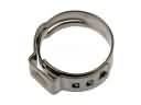 2008 Toyota 4Runner Fuel Line Clamps
 2008 Toyota 4Runner Power Steering Reservoir
 2008 Toyota 4Runner Rack and Pinion Boot
 2008 Toyota 4Runner Steering Column
 2008 Toyota 4Runner Steering Column Cover
 2008 Toyota 4Runner Tie Rod End
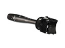 2008 Toyota 4Runner Turn Signal Switch
 2008 Toyota 4Runner Wiper Switch