×
ToyotaParts- Hello
- Login or Register
- Quick Links
- Live Chat
- Track Order
- Parts Availability
- RMA
- Help Center
- Contact Us
- Shop for
- Toyota Parts
- Scion Parts
My Garage
My Account
Cart
OEM 2004 Toyota 4Runner Rack And Pinion
Steering Rack And Pinion- Select Vehicle by Model
- Select Vehicle by VIN
Select Vehicle by Model
orMake
Model
Year
Select Vehicle by VIN
For the most accurate results, select vehicle by your VIN (Vehicle Identification Number).
1 Rack And Pinion found


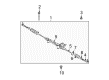
2004 Toyota 4Runner Link Assembly, Power Steering
Part Number: 44200-35061$653.07 MSRP: $957.08You Save: $304.01 (32%)Ships in 1-3 Business DaysProduct Specifications- Other Name: Steering Gearbox
- Replaces: 44200-35060
- Part Name Code: 44200
- Item Weight: 20.40 Pounds
- Item Dimensions: 62.6 x 9.4 x 6.3 inches
- Condition: New
- Fitment Type: Direct Replacement
- SKU: 44200-35061
- Warranty: This genuine part is guaranteed by Toyota's factory warranty.
2004 Toyota 4Runner Rack And Pinion
Looking for affordable OEM 2004 Toyota 4Runner Rack And Pinion? Explore our comprehensive catalogue of genuine 2004 Toyota 4Runner Rack And Pinion. All our parts are covered by the manufacturer's warranty. Plus, our straightforward return policy and speedy delivery service ensure an unparalleled shopping experience. We look forward to your visit!
2004 Toyota 4Runner Rack And Pinion Parts Q&A
- Q: How to Overhaul the Rack and Pinion in Power Steering Systems on 2004 Toyota 4Runner?A: The power steering link assembly overhaul process starts with disconnecting the battery negative terminal and steering the front wheels to a straight position. Fish out the horn button assembly together with steering wheel assembly through SST 09950-50013 (09951-05010/09952-05010/09953-05020/09954-05021) as well as steering column cover lower, turn signal switch assembly, spiral cable sub-assembly, and front wheel. The first step requires disassembling the engine under cover assembly rear with six bolts and then proceeding to remove the engine under cover sub-assembly No.1 using four bolts. To disconnect the left tie rod end sub-assembly remove the cotter pin then the nut while using SST 09628-62011 to detach it from the steering knuckle arm. Apply the identical method to disassemble the right tie rod end sub-assembly. The next step involves taking out the steering intermediate shaft sub-assembly No.2 followed by disconnection of the pressure feed tube assembly with SST 09023-12700 and finally removing two bolts to split the pressure feed tube assembly from the frame sub-assembly. Remove the clip from the rack and pinion outlet return tube and hose to disconnect it before using SST 09023-12700 to remove the outlet return tube. A proper removal involves letting the 2 bolts and 2 nuts free to disassemble the power steering link assembly while deliberately turning the bolts instead of the nuts because of the detent. The power steering link assembly needs fixing with 2 turn pressure tubes using SST 09023-38200 and an SST 09612-00012 vise clamp to maintain the Rack And Pinion assembly position. The sub-assembly needs removal of its left and right tie rod ends while unfastening the lock nuts before marking their current positions. Separate the clamps and clips from both steering rack boots on the left and right sides before removing the boots. The rack and pinion end sub-assembly removal requires staking the washer backward while keeping the rack and pinion still with a spanner tool and using SST 09922-10010 to detach the rack end. Use SST 09922-10010 to remove the rack guide before breaking the 2 power steering control valve retaining bolts for extraction of the assembly. To detach the bearing guide nut, position the assembly into a soft jaw vise and use SST 09631-20060. Drive out the oil seal by using SST 09950-60010 (09951-00300) and 09950-70010 (09951-07100) after removing the O-ring and dust cover. Wind vinyl tape around the control valve shaft and tap out the valve assembly with the bearing guide nut. Get rid of the 4 Teflon rings from the control valve assembly before you extract the union seat out of the control valve housing. Use SST 09950-70010 (09951-07150) and 09950-60010 (09951-00250) to extract the upper oil seal after which the cylinder end stopper can be taken out with SST 09631-20120. SST 09950-70010 (09951-07200) should be used to press out the rack and pinion and oil seal after ensuring the rack will not fall. The vent hole of the power steering rack should be inspected for clogs while torque measurements should be performed on both left and right tie rod end sub-assemblies by flipping their ball joint studs. Begin by removing the rack and pinion piston ring after which install new Teflon and O-ring components that require coating with power steering fluid before installation process can begin. Rephrase the following sentence. The rack installation begins by applying power steering fluid to SST 09631-00350 and then fitting it to the rack before completely seating the rack inside the housing. Place the new oil seal lip with proper orientation and hit the cylinder end stopper with a hammer which has received power steering fluid coating before installing a new O-ring. Torque the stopper with SST 09631-20120 to 145 Nm (1,479 kgf-cm, 107 ft. lbs.) before testing the equipment for air leaks using SST 09631-12071 (09633-00010) under vacuum.
Related 2004 Toyota 4Runner Parts
 2004 Toyota 4Runner Steering Wheel
 2004 Toyota 4Runner Power Steering Pump
 2004 Toyota 4Runner Steering Shaft
 2004 Toyota 4Runner Drag Link
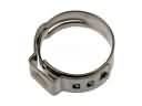 2004 Toyota 4Runner Fuel Line Clamps
 2004 Toyota 4Runner Power Steering Reservoir
 2004 Toyota 4Runner Rack and Pinion Boot
 2004 Toyota 4Runner Steering Column
 2004 Toyota 4Runner Steering Column Cover
 2004 Toyota 4Runner Tie Rod End
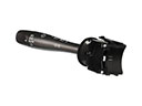 2004 Toyota 4Runner Turn Signal Switch
 2004 Toyota 4Runner Wiper Switch