×
ToyotaParts- Hello
- Login or Register
- Quick Links
- Live Chat
- Track Order
- Parts Availability
- RMA
- Help Center
- Contact Us
- Shop for
- Toyota Parts
- Scion Parts
My Garage
My Account
Cart
OEM 2005 Toyota 4Runner Rack And Pinion
Steering Rack And Pinion- Select Vehicle by Model
- Select Vehicle by VIN
Select Vehicle by Model
orMake
Model
Year
Select Vehicle by VIN
For the most accurate results, select vehicle by your VIN (Vehicle Identification Number).
2 Rack And Pinions found


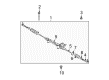
2005 Toyota 4Runner Steering Gear
Part Number: 44200-35070$976.36 MSRP: $1430.87You Save: $454.51 (32%)Ships in 1-2 Business DaysProduct Specifications- Other Name: Link Assembly, Power Steering; Rack and Pinion Assembly; Steering Gearbox; Gear Assembly
- Part Name Code: 44200
- Item Weight: 49.50 Pounds
- Item Dimensions: 52.7 x 11.1 x 6.9 inches
- Condition: New
- Fitment Type: Direct Replacement
- SKU: 44200-35070
- Warranty: This genuine part is guaranteed by Toyota's factory warranty.

2005 Toyota 4Runner Link Assembly, Power Steering
Part Number: 44200-35061$653.07 MSRP: $957.08You Save: $304.01 (32%)Ships in 1-3 Business DaysProduct Specifications- Other Name: Steering Gearbox
- Replaces: 44200-35060
- Part Name Code: 44200
- Item Weight: 20.40 Pounds
- Item Dimensions: 62.6 x 9.4 x 6.3 inches
- Condition: New
- Fitment Type: Direct Replacement
- SKU: 44200-35061
- Warranty: This genuine part is guaranteed by Toyota's factory warranty.
2005 Toyota 4Runner Rack And Pinion
Looking for affordable OEM 2005 Toyota 4Runner Rack And Pinion? Explore our comprehensive catalogue of genuine 2005 Toyota 4Runner Rack And Pinion. All our parts are covered by the manufacturer's warranty. Plus, our straightforward return policy and speedy delivery service ensure an unparalleled shopping experience. We look forward to your visit!
2005 Toyota 4Runner Rack And Pinion Parts Q&A
- Q: How to Overhaul the Power Rack and Pinion Link Assembly on 2005 Toyota 4Runner?A: The installation of the power rack and pinion control valve upper oil seal involves dipping its new lip in power steering fluid before embedding it with SST 09950-60010 (09951-00180, 09951-00320, 09952-06010) or 09950-70010 (09951-07150) while ensuring the correct orientation. The chosen SST should be utilized to insert a new bearing which has been coated with molybdenum disulfide lithium base grease. To install the power rack and pinion control valve start by applying gentle plastic hammer taps on a new union seat followed by cleaning the control valve housing from dust and treating the rings with power steering fluid before expanding the four new rings before placing them in the valve assembly. The tapered end of SST 09631-20081 should be carefully inserted over the rings while power steering fluid coats the teflon rings followed by vinyl tape protection of the oil seal lip before pushing the valve assembly into the housing. Rephrase the instructions by applying power steering fluid to both the new O-ring and oil seal lip and insert the oil seal using SST 09950-60010 (09951-00390) or 09950-70010 (09951-07100). Finally mount the control valve assembly into a vise. First apply SST 09631-20060 to guide nut then torque it with 25 Nm (250 kgf-cm, 18 ft. lbs.) after which stake the nut with punch and hammer and place a new O-ring onto the valve housing. Provided molybdenum disulfide base grease in an amount of 2 g (0.07 oz.) is applied to the needle roller bearing inside the rack housing before final installation using two bolts tightened to 18 Nm (184 kgf-cm, 13 ft. lbs.). Apply part No. 08833-00080 (Three Bond 1344 or Loctite 242 or equivalent) on the rack guide spring cap threads then attach it with a 24 mm hexagon wrench until it reaches 25 Nm (250 kgf-cm, 18 ft. lbs.) before turning the cap by 30°. Adjust the total preload by installing temporarily the RH and LH rack ends then loosening the cap until the rack guide spring is not functional using SST 09616-00011 until achieving preload within 1.35 - 1.55 Nm range (13.77 - 15.81 kgf-cm, 11.94 - 13.71 inch lbs.). First, thread lock the sealant onto the lock nut threads. Then mount the lock nut temporarily with SST 09922-10010 at 65 Nm (660 kgf-cm, 48 ft. lbs.). Check the total preload once again before taking off the RH and LH rack ends. A wire should be used to check for blockage in the power steering rack through its vent hole. Position a new claw washer then loosely install the rack end before torquing the rack end LH and RH to 98 Nm (1,000 kgf-cm, 72 ft. lbs.) using SST 09922-10010. Follow the washer stake procedure by using a brass bar along with a hammer but maintain distance from the rack surface. Perform the same process on the other side. Place both steering rack boots into position LH and RH while avoiding damage to the boot material and twisting the boot shapes then secure each side with its respective clips. Use SST 09616-00011 to inspect power steering rack and pinion assembly components and maintain a smooth stretch of rack boot when control valve shaft rotates while applying MP grease prior to dust cover installation. SST 09023-38200 allows the installation of steering turn pressure tubes which should be torqued to 23 Nm (230 kgf-cm, 17 ft.lbs.). This installation phase requires the subsequent installation of tie rod end sub-assemblies LH and RH with nut torques at 88 Nm (897 kgf-cm, 65 ft.lbs.). Install the power steering link assembly by turning the bolt and not the nut during installation while torquing two bolts and nuts to 100 Nm (1,020 kgf-cm, 74 ft. lbs.). At first stabilize the suspension then connect the steering rack and pinion outlet return tube using SST 09023-12700 with a torque of 40 Nm (410 kgf-cm, 30 ft. lbs.) before installing the hose with its clip. Secure the frame pressure feed tube assembly using two bolts at 28 Nm before adding SST 09023-12700 to lock the flare nut at 40 Nm. Install the steering intermediate shaft sub-assembly No.2 before connecting the tie rod end sub-assembly LH to its steering knuckle arm while tightening the nut and insert the cotter pin and torquing the nut to 91 Nm (928 kgf-cm, 67 ft. lbs.). First complete the installation of engine under cover sub-assembly No.1 through four bolts followed by engine under cover assembly rear with six bolts. The front wheel should be installed with 110 Nm of torque (1,122 kgf-cm, 81 ft. lbs.) while positioning the front wheels straight ahead before installing the turn signal switch assembly then the spiral cable sub-assembly followed by the lower steering column cover while centering the spiral cable and installing the steering wheel assembly. The center point of the steering wheel requires inspection followed by horn button assembly inspection and SRS warning light check. Next, power steering fluid should be added before bleaching the fluid and looking for leaks. Finally, front wheel alignment needs inspection and adjustment.
Related 2005 Toyota 4Runner Parts
 2005 Toyota 4Runner Steering Wheel
 2005 Toyota 4Runner Power Steering Pump
 2005 Toyota 4Runner Steering Shaft
 2005 Toyota 4Runner Drag Link
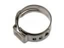 2005 Toyota 4Runner Fuel Line Clamps
 2005 Toyota 4Runner Power Steering Reservoir
 2005 Toyota 4Runner Rack and Pinion Boot
 2005 Toyota 4Runner Steering Column
 2005 Toyota 4Runner Steering Column Cover
 2005 Toyota 4Runner Tie Rod End
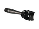 2005 Toyota 4Runner Turn Signal Switch
 2005 Toyota 4Runner Wiper Switch