×
ToyotaParts- Hello
- Login or Register
- Quick Links
- Live Chat
- Track Order
- Parts Availability
- RMA
- Help Center
- Contact Us
- Shop for
- Toyota Parts
- Scion Parts
My Garage
My Account
Cart
OEM Toyota Land Cruiser Rack And Pinion
Steering Gear- Select Vehicle by Model
- Select Vehicle by VIN
Select Vehicle by Model
orMake
Model
Year
Select Vehicle by VIN
For the most accurate results, select vehicle by your VIN (Vehicle Identification Number).
5 Rack And Pinions found


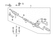
Toyota Land Cruiser Steering Gear Part Number: 44200-60170
$763.96 MSRP: $1119.59You Save: $355.63 (32%)Ships in 1-3 Business Days

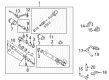
Toyota Land Cruiser Gear Assembly, Power Steering(For Rack & Pinion) Part Number: 44250-60050
$685.64 MSRP: $1004.81You Save: $319.17 (32%)Ships in 1-3 Business Days

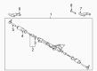
Toyota Land Cruiser Link Assembly, Power Steering Part Number: 44200-60100
$680.83 MSRP: $997.77You Save: $316.94 (32%)
Toyota Land Cruiser Rack, Front Part Number: 44204-60020
$389.74 MSRP: $571.17You Save: $181.43 (32%)Ships in 1-3 Business Days
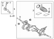
Toyota Land Cruiser Gear Assembly, Electric Part Number: 44250-60370
$1199.34 MSRP: $1757.65You Save: $558.31 (32%)Ships in 1-2 Business Days
Toyota Land Cruiser Rack And Pinion
Choose genuine Rack And Pinion that pass strict quality control tests. You can trust the top quality and lasting durability. Shopping for OEM Rack And Pinion for your Toyota Land Cruiser? Our website is your one-stop destination. We stock an extensive selection of genuine Toyota Land Cruiser parts. The price is affordable so you can save more. It only takes minutes to browse and find the exact fit. Easily add to cart and check out fast. Our hassle-free return policy will keep you stress-free. We process orders quickly for swift delivery. Your parts will arrive faster, so you can get back on the road sooner.
Toyota Land Cruiser Rack And Pinion Parts and Q&A
- Q: How to service and repair the Rack And Pinion on Toyota Land Cruiser?A:The Rack And Pinion assembly needs to be fixed in a vise using Special Service Tool: 09630-00014 (09631-00142) while being careful not to apply excessive force. Users should remove both turn pressure tubes using Special Service Tool: 09633-00020 before continuing with the tube support retainer bolt and retainer removal sequence. The clamps securing the rack boots must be loosened with pliers before removing both boots and marking the boots' right and left sides for their original positions. Screwdriver and a hammer allow you to carefully stake the washer on both RH and LH rack ends until the rack and pinion remains steady with the help of a spanner that enables removal of the rack end using Special Service Tool: 09922-10010. Repeating this process for the LH rack end. Start by unlocking the rack guide spring cap lock nut and proceeding to take out the rack guide spring cap and rack guide spring and rack guide sub-assembly one after the other before finally removing the dust cover. The operative must first place matchmarks on both components then remove the control valve assembly by loosening the bearing guide nut with Special Service Tool: 09631-20060 and tapping it out with a plastic hammer. To remove the components, first use Special Service Tool: 09922-10010 to detach the cylinder end stopper and spacer, then press out the rack and pinion and oil seal using Special Service Tool: 09950-70010 (09951-07200) without letting the rack fall. The procedure requires use of the tools Special Service Tool: 09950-60010 (09951-00260), 09950-70010 (09951-07150) to inspect rack and pinion conditions for wear while properly orienting oil seals during installation. The needle roller bearing requires inspection for any sign of damage. Whenever the rack housing shows damage replace it. Check the bearing rotational movement together with the bushing condition and take replacement steps if cracks are detected. Discard the rack and pinion Teflon ring and O-ring while paying attention to protect the grooves during this exchange. Attach power steering fluid or molybdenum disulfide lithium base grease onto parts before using tool 09951-60010 (09951-00350, 09951-00550, 09952-06010) to install the spacer and oil seal properly. First install the rack and pinion along with the oil seal through Special Service Tool: 09631-00350 then proceed to put in the spacer and cylinder end stopper and finish by torquing the stopper to 66 Nm (677 kgf-cm, 49 ft. lbs.) with Special Service Tool: 09922-10010. Run an air-tightness test by using Special Service Tool: 09631-12071 which shows no vacuum change. Fasten the control valve assembly while applying power steering fluid on the teflon rings and O-ring before tightening the bearing guide nut to 25 Nm using 250 kgf-cm and 18 ft. lbs. torque. Set up the control valve housing with its valve assembly where matching marks must be aligned before tightening the bolts to 18 Nm (185 kgf-cm, 13 ft. lbs.). Use seals on the threads before installing the assembled components consisting of dust cover, rack guide sub-assembly, spring and spring cap. Whole spring preload adjustment first requires temporary rack end installation before securing the rack guide spring cap to 25 Nm (250 kgf-cm, 18 ft.lbs.) at a 19° return angle. Apply Special Service Tool: 09616-00010 to adjust preload between 1.3 Nm to 1.8 Nm (13.3 kgf-cm to 18.4 kgf-cm, 11.5 inch lbs.to 16.0 inch lbs.). You must apply sealant to the rack guide spring cap lock nut before torquing it to 51 Nm (521 kgf-cm, 38 ft. lbs.) while verifying the total preload measurement. The last step includes installing rack ends followed by torquing claw washers and rack ends to 76 Nm (770 kgf-cm, 56 ft. lbs.) and washer staking before attaching rack boots with clamps and clips which must have a clear tube hole for installation of the tube support retainer and 2 turn pressure tubes with their specific torque values.
- Q: How to remove and install the Rack And Pinion on Toyota Land Cruiser?A:The first step for removing the rack and pinion is to position the front wheels directly forward before removing the Steering Wheel pad and steering wheel. The first step involves unfastening 7 engine under cover bolts from the No. 1 engine area before moving to the second step which requires you to remove 6 bolts from the No. 2 engine under cover. The RH and LH tie rod ends require disconnection before accessing the engine Oil Filter assembly through the steps of removing two clips along with hoses and two bolts, a nut, a bracket, and an O-ring. To disconnect the No. 2 intermediate shaft assembly first turn the steering wheel to the right position fully and remove the pressure feed tube by unfastening the union bolt with its gasket. The procedure to disconnect the return tube requires using Special Service Tool: 09631-22020. Uninstall the bracket and grommet through the removal of two bolts before removing the tube clamp by disconnecting its single bolt. Begin by marking the tie rod end and other components. After that, loosen the lock nut then remove the tie rod end and lock nut from each side. The rack and pinion assembly removal requires disconnection of 2 bolts, 2 nuts and 2 washers followed by sliding rack and pinion assembly right and pulling out left side. Installation begins with fitting the rack and pinion assembly through its 2 bolts, 2 nuts, and 2 washers then torquing them to 100 Nm (1,020 kgf-cm, 74 ft. lbs.). Proceed to the installation of RH and LH tie rod ends along with their respective lock nuts by properly aligning matchmarks before torquing the nut until it reaches 55 Nm (560 kgf-cm, 41 ft. lbs.). Home in the bolt of the tube clamp before torquing to 18 Nm (184 kgf-cm, 13 ft. lbs.) and finish the installation with 2 new bolts of the bracket and grommet torqued to 100 Nm (1,020 kgf-cm, 74 ft. lbs.). Fitting the return tube requires Special Service Tool 09631-22020 for torquing to 58 Nm (587 kgf.cm, 43 ft. lb.) while the tool remains parallel to the torque wrench. Attach the pressure feed tube by installing a new gasket on the union bolt which needs a torques setting of 49 Nm (500 kgf-cm and 36 ft. lbs.) while making sure the stopper contacts the rack and pinion assembly. First reconnect the No. 2 intermediate shaft assembly then install the engine oil filter assembly with new O-ring and 2 bolts and a nut which must be torqued to 18 Nm (184 kgf-cm, 13 ft. lbs.) while reconnecting all hoses along with their clips. After restoring the RH and LH tie rod ends the technician will install under cover No. 2 using six bolts and finally install under cover No. 1 with seven bolts. Straighten the front wheels toward the center of the vehicle while you place the spiral cable in position and install the steering wheel by tightening the set nut but only briefly before cabling the connector. After power steering bleeding the technician should check steering wheel center alignment followed by a 34 Nm (350 kgf-cm, 25 ft. lbs.) torque setting of the steering wheel set nut. They should then install the steering wheel pad and perform a front wheel alignment check.
")

Related Toyota Land Cruiser Parts
 Toyota Land Cruiser Power Steering Pump
 Toyota Land Cruiser Tie Rod End
 Toyota Land Cruiser Center Link
 Toyota Land Cruiser Drag Link
 Toyota Land Cruiser Pitman Arm
 Toyota Land Cruiser Power Steering Control Valve
 Toyota Land Cruiser Power Steering Hose
 Toyota Land Cruiser Power Steering Reservoir
 Toyota Land Cruiser Rack and Pinion Boot
 Toyota Land Cruiser Steering Column
 Toyota Land Cruiser Steering Column Cover
 Toyota Land Cruiser Windshield Wiper Switch