×
ToyotaParts- Hello
- Login or Register
- Quick Links
- Live Chat
- Track Order
- Parts Availability
- RMA
- Help Center
- Contact Us
- Shop for
- Toyota Parts
- Scion Parts
My Garage
My Account
Cart
OEM 2004 Toyota Land Cruiser Rack And Pinion
Steering Rack And Pinion- Select Vehicle by Model
- Select Vehicle by VIN
Select Vehicle by Model
orMake
Model
Year
Select Vehicle by VIN
For the most accurate results, select vehicle by your VIN (Vehicle Identification Number).
1 Rack And Pinion found


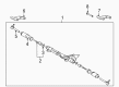
2004 Toyota Land Cruiser Link Assembly, Power Steering
Part Number: 44200-60100$680.83 MSRP: $997.77You Save: $316.94 (32%)Product Specifications- Other Name: Rack and Pinion Assembly; Steering Gearbox
- Part Name Code: 44200
- Item Weight: 38.20 Pounds
- Item Dimensions: 52.2 x 11.0 x 6.8 inches
- Condition: New
- Fitment Type: Direct Replacement
- SKU: 44200-60100
- Warranty: This genuine part is guaranteed by Toyota's factory warranty.
2004 Toyota Land Cruiser Rack And Pinion
Looking for affordable OEM 2004 Toyota Land Cruiser Rack And Pinion? Explore our comprehensive catalogue of genuine 2004 Toyota Land Cruiser Rack And Pinion. All our parts are covered by the manufacturer's warranty. Plus, our straightforward return policy and speedy delivery service ensure an unparalleled shopping experience. We look forward to your visit!
2004 Toyota Land Cruiser Rack And Pinion Parts Q&A
- Q: How to remove and install the Rack And Pinion on 2004 Toyota Land Cruiser?A: The process to remove the rack and pinion starts with facing front wheels straight ahead followed by pad and wheel removal before proceeding to remove engine under covers. The task involves eliminating the 7 bolts securing the No. 1 engine under cover before proceeding to the No. 2 engine under cover by removing its 6 bolts. The engine oil filter assembly removal procedure begins with disconnecting 2 clips and hoses followed by the removal of 2 bolts and a nut along with the bracket which allows for the O-ring extraction. You must first rotate the steering wheel to the right until it reaches maximum right turn then disconnect the pressure feed tube through removal of its union bolt together with gasket. The Special Service Tool: 09023-38400 enables the removal of the return tube. Placing matchmarks on tie rod ends and rack ends first, you can free the lock nuts to extract both the tie rod end and lock nut and do the same procedure on the opposite side. The Rack And Pinion assembly removal starts by removing Rack And Pinion assembly set bolts, nuts, washers while sliding the Rack And Pinion to the right and drawing out the left side from the member. The first installation step involves putting on the Rack And Pinion assembly before torquing the 2 new Rack And Pinion assembly set bolts, nuts, and washers to 120 Nm (1,250 kgf-cm, 89 ft. lbs.). When installing tie rod ends for both sides, torque the lock nuts to 55 Nm (560 kgf-cm, 41 ft. lbs.) after setting the toe-in. Follow this by attaching the tube clamp and torquing its bolt to 18 Nm (180 kgf-cm, 13 ft. lbs.). Then, use Special Service Tool: 09023-38400 to join the return tube and torque it to 50 Nm (510 kgf-cm, 37 ft. lbs.). Precise measurements require that the torque wrench features 300 mm (11.81 inch) as its fulcrum length. The pressure feed tube should be connected with the stopper touching the Rack And Pinion assembly while torquing the union bolt with new gasket to 42 Nm (430 kgf-cm, 31 ft. lbs). After installing a new O-ring on the engine oil filter assembly, reinstall the 2 clips and hoses while torquing the 2 bolts and nut with bracket to 18 Nm (180 kgf-cm, 13 ft. lbs.). Reattach the engine undercovers by tightening six bolts on the No. 2 position followed by seven bolts on the No. 1 cover. Jacking the vehicle and facing its front wheels straight ahead enables the technician to center a spiral cable before installing the steering wheel while matching marks, tightening the wheel set nut temporarily and connecting connectors. Power steering system bleeding must occur before checking steering wheel position while tightening the set nut to 50 Nm (510 kgf-cm, 37 ft. lbs.). The last step involves installing the steering wheel pad then examining the front wheel alignment and completing zero point calibration for yaw rate as well as deceleration sensors.
Related 2004 Toyota Land Cruiser Parts
 2004 Toyota Land Cruiser Steering Wheel
 2004 Toyota Land Cruiser Power Steering Pump
 2004 Toyota Land Cruiser Tie Rod End
 2004 Toyota Land Cruiser Drag Link
 2004 Toyota Land Cruiser Power Steering Hose
 2004 Toyota Land Cruiser Power Steering Reservoir
 2004 Toyota Land Cruiser Rack and Pinion Boot
 2004 Toyota Land Cruiser Steering Angle Sensor
 2004 Toyota Land Cruiser Steering Column Cover
 2004 Toyota Land Cruiser Steering Shaft
 2004 Toyota Land Cruiser Wiper Switch