×
ToyotaParts- Hello
- Login or Register
- Quick Links
- Live Chat
- Track Order
- Parts Availability
- RMA
- Help Center
- Contact Us
- Shop for
- Toyota Parts
- Scion Parts
My Garage
My Account
Cart
OEM 2006 Toyota Land Cruiser Rack And Pinion
Steering Rack And Pinion- Select Vehicle by Model
- Select Vehicle by VIN
Select Vehicle by Model
orMake
Model
Year
Select Vehicle by VIN
For the most accurate results, select vehicle by your VIN (Vehicle Identification Number).
1 Rack And Pinion found


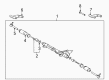
2006 Toyota Land Cruiser Link Assembly, Power Steering
Part Number: 44200-60100$680.83 MSRP: $997.77You Save: $316.94 (32%)Product Specifications- Other Name: Rack and Pinion Assembly; Steering Gearbox
- Part Name Code: 44200
- Item Weight: 38.20 Pounds
- Item Dimensions: 52.2 x 11.0 x 6.8 inches
- Condition: New
- Fitment Type: Direct Replacement
- SKU: 44200-60100
- Warranty: This genuine part is guaranteed by Toyota's factory warranty.
2006 Toyota Land Cruiser Rack And Pinion
Looking for affordable OEM 2006 Toyota Land Cruiser Rack And Pinion? Explore our comprehensive catalogue of genuine 2006 Toyota Land Cruiser Rack And Pinion. All our parts are covered by the manufacturer's warranty. Plus, our straightforward return policy and speedy delivery service ensure an unparalleled shopping experience. We look forward to your visit!
2006 Toyota Land Cruiser Rack And Pinion Parts Q&A
- Q: How to service and repair the power Rack And Pinion on 2006 Toyota Land Cruiser?A: Start your power steering rack and pinion service and repair work by taking out the steering wheel assembly to protect the spiral cable before disconnecting the negative battery terminal for 90 seconds to deactivate Air Bags. Straighten your front wheels before you remove the steering wheel pad along with the assembly as well as the No. 1 and No. 2 engine under covers by undoing their respective bolts. To start, disconnect both left and right tie rod end sub-assemblies and remove the engine oil filter assembly through clip disconnection of hoses and the separation of bolts with bracket. The first step to disconnected the No. 2 intermediate shaft assembly involves turning the steering wheel right until it reaches complete right position. Then, use the union bolt removal to disconnect the pressure feed tube assembly. Finally, use Special Service Tool: 09023-38401 to disconnect the return tube assembly. Disassemble the tie rod end sub-assemblies from both sides of the vehicle by noting their positions and freeing the lock nuts to extract them. Afterward put away the power steering rack and pinion assembly by removing the Rack And Pinion assembly set bolts and nuts followed by washers while moving the Rack And Pinion assembly to the right side to extract this left side. To accomplish disassembly fix the power steering rack and pinion assembly within a vise using Special Service Tools: 09630-00014 (09631-00142). Then use Special Service Tool: 09023-38201 to unfasten the turn pressure tube assembly before carefully removing the clip and rack boot and clamp without damaging the boot. After using a screwdriver and hammer to remove the steering rack end you should stabilize the rack with a spanner while using Special Service Tool: 09922-10010 to complete rod end removal before taking off the claw washer. Use Special Service Tool: 09922-10010 to remove the rack guide spring cap lock nut then proceed to take out the rack guide spring cap followed by the rack guide spring and dust cover. During this process mark both the valve housing and rack housing then detach all bolts to extract the control valve housing and valve assembly while removing the O-ring. To remove the control valve assembly begin with loosening the bearing guide nut using Special Service Tool: 09631-20060 and tap the valve assembly with a plastic hammer until the nut and O-ring can be removed. Special Service Tool: 09922-10010 allows the removal of the cylinder end stopper and spacer before proceeding to press out the rack and oil seal with Special Service Tool: 09950-70010 (09951-07200) without dropping the rack. The steering rack should be inspected for runout and wear while the bearing must be checked for damage before application of molybdenum disulfide lithium base grease. Use Special Service Tool: 09950-60010 (09951-00260) to install the oil seal correctly along with the bearing while inspecting the bush for cracks that require necessary grease application. The steering rack receives its teflon ring and O-ring while avoiding groove damage before new rings are installed onto the control valve assembly through Special Service Tool: 09631-20081's tapered end. A screw extractor will remove the union seat from the control valve housing before lightly tapping in a new one. Reassembly begins with coating the indicated parts with power steering fluid or grease followed by installing the power steering rack and pinion housing sub-assembly with Special Service Tool: 09631-00350 while installing the oil seal exactly. Before installation of the spacer and cylinder end stopper check the O-ring receives fluid coating before torquing the stopper to 110 Nm (1,122 kgf-cm, 81 ft. lbs.) using Special Service Tool: 09922-10010. Use Special Service Tool: 09631-12071 to conduct an air tightness test before installing the control valve assembly while making sure teflon rings have fluid coating and the assembly enters the housing without any damage. The bearing guide nut requires torqueing to 24.5 Nm (250 kgf-cm, 18 ft. lbs.) followed by staking it using a punch. Fasten the control valve housing assembly with valve components by placing matchmarks in alignment before torquing bolts at 18 Nm force (180 kgf-cm, 13 ft. lbs.). The power steering rack and pinion housing oil seal must be installed with the rack guide sub-assembly and rack guide spring along with rack guide spring cap while using sealant for the threads. First temporarily put in the rack ends and tighten the rack guide spring cap to 25 Nm (250 kgf-cm, 18 ft. lbs.) then rotate the cap nineteen degrees. Special Service Tool: 09616-00011 should be used to adjust the preload within specifications before installing the rack guide spring cap lock nut with sealant and torque it to 52 Nm (520 kgf-cm, 38 ft. lbs.). Position the claw washer underneath the steering rack grooves before attaching the rack end and torque it to 99 Nm (1,014 kgf-cm, 74 ft. lbs.). Use Special Service Tool: 09023-38201 to install the two turn pressure tubes by torquing them to 23 Nm (230 kgf-cm, 17 ft. lbs.). The tube hole must be free of obstructions. The installation requires torqueing new Rack And Pinion assembly set bolts and nuts and washers to 120 Nm (1,250 kgf-cm, 89 ft. lbs.) before installing the right and left tie rod ends and toe-in adjustment followed by nut torque to 55 Nm (560 kgf-cm, 41 ft. lbs.). Use Special Service Tool: 09023-38401 to connect the return tube assembly and apply 50 Nm torque (510 kgf-cm, 37 ft. lbs.). After installing the tube clamp give the bolt a torque of 18 Nm (180 kgf-cm, 13 ft. lbs.). Secure the pressure feed tube by placing the stopper on the power steering rack and pinion assembly and tighten the unit bolt to 42 Nm (430 kgf-cm, 31 ft. lbs.). Finally, connect the No. 2 intermediate shaft assembly, install the engine oil filter assembly, connect the left and right tie rod end sub-assemblies, install the engine under covers, face the front wheels straight ahead, center the spiral cable, install the steering wheel assembly, bleed air from the power steering system, check the steering wheel center point, torque the steering wheel set nut to 50 Nm (510 kgf-cm, 37 ft. lbs.), install the steering wheel pad, connect the cable to the negative battery terminal, perform initialization, and check the front wheel alignment.
Related 2006 Toyota Land Cruiser Parts
 2006 Toyota Land Cruiser Steering Wheel
 2006 Toyota Land Cruiser Power Steering Pump
 2006 Toyota Land Cruiser Tie Rod End
 2006 Toyota Land Cruiser Drag Link
 2006 Toyota Land Cruiser Power Steering Hose
 2006 Toyota Land Cruiser Power Steering Reservoir
 2006 Toyota Land Cruiser Rack and Pinion Boot
 2006 Toyota Land Cruiser Steering Angle Sensor
 2006 Toyota Land Cruiser Steering Column Cover
 2006 Toyota Land Cruiser Steering Shaft
 2006 Toyota Land Cruiser Wiper Switch