×
ToyotaParts- Hello
- Login or Register
- Quick Links
- Live Chat
- Track Order
- Parts Availability
- RMA
- Help Center
- Contact Us
- Shop for
- Toyota Parts
- Scion Parts
My Garage
My Account
Cart
OEM 2006 Toyota Land Cruiser Power Steering Pump
Power Steering Pump Unit- Select Vehicle by Model
- Select Vehicle by VIN
Select Vehicle by Model
orMake
Model
Year
Select Vehicle by VIN
For the most accurate results, select vehicle by your VIN (Vehicle Identification Number).
1 Power Steering Pump found


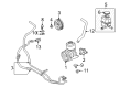
2006 Toyota Land Cruiser Pump Assembly, Vane
Part Number: 44310-60390$365.46 MSRP: $535.58You Save: $170.12 (32%)Ships in 1-3 Business DaysProduct Specifications- Other Name: Power Steering Pump
- Part Name Code: 44310
- Item Weight: 5.00 Pounds
- Item Dimensions: 8.4 x 6.3 x 5.8 inches
- Condition: New
- Fitment Type: Direct Replacement
- SKU: 44310-60390
- Warranty: This genuine part is guaranteed by Toyota's factory warranty.
2006 Toyota Land Cruiser Power Steering Pump
Looking for affordable OEM 2006 Toyota Land Cruiser Power Steering Pump? Explore our comprehensive catalogue of genuine 2006 Toyota Land Cruiser Power Steering Pump. All our parts are covered by the manufacturer's warranty. Plus, our straightforward return policy and speedy delivery service ensure an unparalleled shopping experience. We look forward to your visit!
2006 Toyota Land Cruiser Power Steering Pump Parts Q&A
- Q: How to service and repair the power steering pump on 2006 Toyota Land Cruiser?A: The first step to service and repair the power steering pump requires removing the engine under covers at No. 1 and No. 2 positions by uninstalling 7 and 8 bolts each. Start by removing the air cleaner assembly with its air cleaner hose through disconnecting the MAF meter connector along with hoses then loosening the clamp and removing three bolts. Tighten the drive belt tensioner by rotating it counterclockwise and remove the drive belt from its position. Let go of the vacuum hose through two clip removal and detach the return hose by removing its clip. First separate the pressure feed tube assembly using union bolt removal and 2 gasket removal steps and then proceed to remove the vane pump assembly through bolt removal of 3 pieces. The vane pump assembly needs to be placed into a vise while holding it with Special Service Tool: 09630-00014 (09631-00132) for disassembly. Inspect the rotating torque of the pump to ensure it stays under 0.3 Nm (2.8 kgf-cm, 2.4 inch lbs.). A 27 mm socket wrench will separate the pressure port union from the front housing after the removal of the flow control valve and its respective O-ring. The power steering suction port union requires bolt removal with an O-ring for detachment. After removing the compression spring from the front housing the technician must loosen 4 bolts to detach the rear housing before extracting the gasket. You must remove the snap ring before extracting the cam ring and ten vane plates and vane pump rotor. Use a micrometer and caliper gauge to check the oil clearance both between front and rear housing vane pump shaft and bushings. When measuring the clearance you must keep to standard 0.020 to 0.077 mm (0.0008 to 0.00303 inch) and maximum 0.070 mm (0.0028 inch) for front housing and 0.080 mm (0.0032 inch) for rear housing; a new vane pump assembly needs installation if clearances exceed limits. Check ten plates for minimal thickness of 1.405 mm (0.0553 inch) while measuring their height and length. Examine the rotor groove clearance against the plate to confirm it stays under 0.03 mm (0.0012 inch). The inspection of the flow control valve requires application of power steering fluid followed by compressed air test at 392 to 490 kPa (4 to 5 kgf/cm2, 57 to 71 psi) to check for smooth operation and leakage; replace the vane pump assembly if necessary. The free spring length must measure at least 31.3 mm (1.2323 inch) or the spring should be replaced. For replacement install the new oil seal using a screwdriver equipped with vinyl tape after applying power steering fluid to the lip edge. Insert it properly by using Special Service Tools 09950-60010 (09951-00280) and 09950-70010 (09951-07100). The correct orientation must be maintained. Place the specified steering fluid on components before installing the vane pump shaft first followed by the side plate featuring new O-rings and the cam ring pointing outward and finally the vane pump rotor with outwards-facing inscription while adding a new snap ring. To install the vane plates insert them with their round sides facing external while the housing gasket receives a power steering fluid coating before installation followed by temporary bolt installation that requires 22 Nm torque force maintained with vise-held vane pump equipment. The flow control valve requiring proper mounting alongside its compression spring should get coated with power steering fluid then added to the union before torquing the pressure port union to 69 Nm (700 kgf-cm, 51 ft. lbs.). Set the suction port union bolt with an O-ring treated in power steering fluid and tighten it to 12 Nm (120 kgf-cm, 9 ft. lbs.). Relay a measurement of vane pump rotational torque before you install the vane pump assembly with a 17 Nm torque (175 kgf-cm, 13 ft. lbs.) on its 3 bolts. Use new gaskets to install the pressure feed tube assembly before tightening the union bolt to 50 Nm (510 kgf-cm, 37 ft. lbs.) while verifying that the stopper makes contact with the vane pump body. After connecting the hose to the clip you must join two vacuum hoses with their respective clips before fitting the fan and generator V-belt and installing the air cleaner assembly and MAF meter connector. Reinstall the engine under covers by tightening the 8 bolts for No. 2 engine before restoring the 7 bolts for No. 1 engine. Also perform power steering system air bleeder procedures.
Related 2006 Toyota Land Cruiser Parts
 2006 Toyota Land Cruiser Steering Wheel
 2006 Toyota Land Cruiser Tie Rod End
 2006 Toyota Land Cruiser Drag Link
 2006 Toyota Land Cruiser Power Steering Hose
 2006 Toyota Land Cruiser Power Steering Reservoir
 2006 Toyota Land Cruiser Rack And Pinion
 2006 Toyota Land Cruiser Rack and Pinion Boot
 2006 Toyota Land Cruiser Steering Angle Sensor
 2006 Toyota Land Cruiser Steering Column Cover
 2006 Toyota Land Cruiser Steering Shaft
 2006 Toyota Land Cruiser Wiper Switch