×
ToyotaParts- Hello
- Login or Register
- Quick Links
- Live Chat
- Track Order
- Parts Availability
- RMA
- Help Center
- Contact Us
- Shop for
- Toyota Parts
- Scion Parts
My Garage
My Account
Cart
OEM 2000 Toyota Land Cruiser Rack And Pinion
Steering Rack And Pinion- Select Vehicle by Model
- Select Vehicle by VIN
Select Vehicle by Model
orMake
Model
Year
Select Vehicle by VIN
For the most accurate results, select vehicle by your VIN (Vehicle Identification Number).
2 Rack And Pinions found


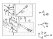
2000 Toyota Land Cruiser Gear Assembly, Power Steering(For Rack & Pinion)
Part Number: 44250-60050$685.64 MSRP: $1004.81You Save: $319.17 (32%)Ships in 1-3 Business DaysProduct Specifications- Other Name: Gear Assembly, Power Steering; Rack and Pinion Assembly; Steering Gearbox
- Part Name Code: 44250
- Item Weight: 40.80 Pounds
- Item Dimensions: 48.8 x 9.5 x 8.1 inches
- Condition: New
- Fitment Type: Direct Replacement
- SKU: 44250-60050
- Warranty: This genuine part is guaranteed by Toyota's factory warranty.

2000 Toyota Land Cruiser Rack, Front
Part Number: 44204-60020$389.74 MSRP: $571.17You Save: $181.43 (32%)Ships in 1-3 Business DaysProduct Specifications- Other Name: Rack Sub-Assembly, Power; Rack And Pinion Rack Gear, Front; Steering Gearbox; Steering Rack; Rack Sub-Assembly, Power Steering
- Position: Front
- Part Name Code: 44204
- Item Weight: 5.40 Pounds
- Item Dimensions: 33.1 x 3.3 x 2.9 inches
- Condition: New
- Fitment Type: Direct Replacement
- SKU: 44204-60020
- Warranty: This genuine part is guaranteed by Toyota's factory warranty.
2000 Toyota Land Cruiser Rack And Pinion
Looking for affordable OEM 2000 Toyota Land Cruiser Rack And Pinion? Explore our comprehensive catalogue of genuine 2000 Toyota Land Cruiser Rack And Pinion. All our parts are covered by the manufacturer's warranty. Plus, our straightforward return policy and speedy delivery service ensure an unparalleled shopping experience. We look forward to your visit!
2000 Toyota Land Cruiser Rack And Pinion Parts Q&A
- Q: How to remove and install the Rack And Pinion on 2000 Toyota Land Cruiser?A: To remove the rack and pinion, keep the front wheels straight, remove the steering wheel pad and wheel followed by the engine under covers. Disconnect tie rod ends, oil filter assembly and disconnect the intermediate shaft. Take out rack and pinion. To install, reverse the process, be sure to assemble the correct torque and alignment.
Related 2000 Toyota Land Cruiser Parts
 2000 Toyota Land Cruiser Steering Wheel
 2000 Toyota Land Cruiser Power Steering Pump
 2000 Toyota Land Cruiser Tie Rod End
 2000 Toyota Land Cruiser Drag Link
 2000 Toyota Land Cruiser Power Steering Control Valve
 2000 Toyota Land Cruiser Power Steering Hose
 2000 Toyota Land Cruiser Power Steering Reservoir
 2000 Toyota Land Cruiser Rack and Pinion Boot
 2000 Toyota Land Cruiser Steering Angle Sensor
 2000 Toyota Land Cruiser Steering Column Cover
 2000 Toyota Land Cruiser Steering Gear Box
 2000 Toyota Land Cruiser Steering Shaft