×
ToyotaParts- Hello
- Login or Register
- Quick Links
- Live Chat
- Track Order
- Parts Availability
- RMA
- Help Center
- Contact Us
- Shop for
- Toyota Parts
- Scion Parts
My Garage
My Account
Cart
OEM Toyota Matrix Rack And Pinion
Steering Gear- Select Vehicle by Model
- Select Vehicle by VIN
Select Vehicle by Model
orMake
Model
Year
Select Vehicle by VIN
For the most accurate results, select vehicle by your VIN (Vehicle Identification Number).
6 Rack And Pinions found

Toyota Matrix Steering Gear Part Number: 45510-02230
$628.55 MSRP: $921.15You Save: $292.60 (32%)Ships in 1-3 Business Days
Toyota Matrix Steering Gear Part Number: 45510-02160
$610.16 MSRP: $894.21You Save: $284.05 (32%)Ships in 1-3 Business Days
Toyota Matrix Steering Gear Part Number: 44250-01041
$634.05 MSRP: $928.99You Save: $294.94 (32%)Ships in 1-3 Business DaysToyota Matrix Steering Gear Part Number: 44250-01021
$653.07 MSRP: $957.08You Save: $304.01 (32%)Ships in 1-3 Business Days
Toyota Matrix Steering Gear Part Number: 45510-02150
$626.62 MSRP: $918.32You Save: $291.70 (32%)
Toyota Matrix Rack Part Number: 44204-02060
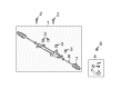
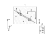
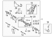
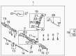
Toyota Matrix Rack And Pinion
Choose genuine Rack And Pinion that pass strict quality control tests. You can trust the top quality and lasting durability. Shopping for OEM Rack And Pinion for your Toyota Matrix? Our website is your one-stop destination. We stock an extensive selection of genuine Toyota Matrix parts. The price is affordable so you can save more. It only takes minutes to browse and find the exact fit. Easily add to cart and check out fast. Our hassle-free return policy will keep you stress-free. We process orders quickly for swift delivery. Your parts will arrive faster, so you can get back on the road sooner.
Toyota Matrix Rack And Pinion Parts and Q&A
- Q: What Are the Comprehensive Steps and Torque Specifications for Disassembling, Inspecting, Reassembling, and Installing the Rack and Pinion on Toyota Matrix?A:Applications must use either power steering fluid or molybdenum disulfide lithium base grease to coat the parts directed by the arrow. Start by disconnecting the negative battery terminal before checking the center front wheel and removing both the horn button assembly and Steering Wheel assembly with tool SST 09950-50013 (along with its variants 09951-05010, 09952-05010, 09953-05020, 09954-05021). Disassemble the front wheels engine under covers and tie rod end sub-assembly LH while removing its cotter pin and nut and using SST 09628-62011 to separate it from the Steering Knuckle. Apply these steps once again to the RH steering compartment. Use SST 09023-38400 to disconnect the steering intermediate shaft and the pressure feed tube assembly. At the same time remove the column hole cover silencer sheet. Use the same SST to detach the return tube sub-assembly and remove its bolt before disconnecting the tube clamp. Users of 4WD vehicles should first remove the bolt then detach the tube clamp. Start by taking off the front stabilizer link assembly LH, then RH, followed by disconnecting both front suspension arm sub-assembly lower No.1 LH, RH units. Also continue with hood sub-assembly and cylinder head cover No.2 removal. You should suspend the engine by mounting the two engine hangers with correct direction bolts then hook up the engine chain hoist. The front suspension crossmember sub-assembly can be removed by disconnecting it from the engine mounting insulator FR and the frame while using a transmission jack to support the assembly and removing its bolts. You must detach the steering column hole cover sub-assembly No.1 along with the steering intermediate shaft by matching and removing its bolts and also disconnect the rack and pinion assembly using bolt removal. Set the rack and pinion assembly in a vise using SST 09612-00012 and detach left and right turn pressure tubes through SST 09023-38200 while taking away the O-rings. When inspecting the tie rod end sub-assemblies for the LH side position the assembly into a vise and apply the nut to the stud bolt followed by flipping the ball joint stud backward and forwards to measure the 5th turn torque which must be between 0.49 - 3.43 Nm (5.0 - 35 kgf-cm, 4.34 - 30.38 inch lbs.). Begin the procedure by removing steering rack boots No.1 and No.2 followed by extraction of the steering rack end sub-assembly with a spanner and SST 09922-10010 while keeping track of the rack ends' right-hand side and left-hand side positions. To extract the power steering control valve one needs to eliminate the rack guide with SST 09922-10010 before removing the rack housing cap and securing the control valve shaft with SST 09616-0011 to detach the bolts and gasket. Wound vinyl tape around the serrated part of the control valve to protect its oil seal lips then you can remove both valve components together. Handler the control valve rings gently when removing them to prevent damage to the groove surface. Remove the power steering control valve upper oil seal by using SST 09950-70010 (09951-07150), 09950-60010 (09951-00260) together with snap ring pliers to extract the cylinder end stopper. SST 09612-24014 (09612-10061) is used to extract the power steering rack without dropping it while removing its O-ring from the bushing. The power steering rack bush sub-assembly and power steering cylinder tube oil seal leave by using SST 09950-60010 (09951-00260) and SST 09950-70010 (09951-07360). The power steering control valve lower bearing must be removed using SST 09950-70010 (09951-07100) together with the center bearing. Examine the power steering rack for run out while also checking the teeth wear and confirm that the maximum run out measure equals 0.1 mm (0.004 inch). Apply molybdenum disulfide lithium base grease to the power steering control valve lower bearing before installing it with SST 09950-60010 (09951-00220, 09951-00280, 09952-06010) and SST 09950-70010 (09951-07100). Also install the power steering cylinder tube oil seal with the correct orientation. Put the power steering rack into position by applying new power piston O-rings and oil seals but avoid forcing the oil seal beyond its designed dimensions. Place the power steering rack bush sub-assembly in its proper orientation with facing direction of the oil seal then add a new snap ring to the cylinder end stopper. Check changes in vacuum during inspection of the rack and pinion assembly with SST 09631-12071 (or 09633-00010). Install both the power steering control valve upper oil seal and upper bearing properly oriented to their direction. Narrow the control valve rings into place carefully while being mindful to avoid over-expanding them before inserting the tapered part of SST over the rings. Attach the control valve to its housing while maintaining the safety of rings and oil seal lip and use SST for fitting the oil seal. The installation requires needle bearing lubrication followed by fresh gasket installation and rack housing cap and housing staking procedure after applying sealant. The rack guide needs installation with compression spring, where a sealing compound must be put on both rack guide spring cap threads. The inspector must check total preload before installing temporary RH and LH rack ends to finalize the torque setting of the rack guide spring cap while making final adjustments when needed. The installation requires SST 09922-10010 to mount the steering rack end sub-assembly but avoid applying grease to the steering rack hole. The installation of boot No.2 and No.1 requires the tie rod end sub-assemblies LH and RH to be connected along with new O-rings being installed in the steering right and left turn pressure tubes. Contact Torque the rack and pinion assembly properly while making sure the bush provides proper installation for 4WD. Place the intermediate steering shaft into position as it aligns corresponding marks while installing the steering column hole cover sub-assembly No.1. Install the front suspension crossmember sub-assembly by tightening its bolts properly and fit the engine mounting insulator RR and FR to the crossmember. The technician must install the front suspension arm sub-assemblies lower No.1 LH and RH along with front stabilizer link assemblies LH and RH and must use SST to link the return and pressure feed tube assemblies. The installation of the steering intermediate shaft and tie rod end sub-assemblies LH and RH includes installation of engine under covers LH and RH and front wheels with proper torque specifications. The wheel center should be inspected before placing the column hole cover silencer sheet. Also add power steering fluid while bleeding the fluid system then check for any fluid leakage. To complete installation put on cylinder head cover No.2, mount the hood sub-assembly before performing hood inspection and adjustment while also centering the spiral cable, placing the steering wheel assembly, horn button assembly, evaluating front wheel alignment and SRS warning light operation.
- Q: How to remove the Rack And Pinion on Toyota Matrix?A:Before taking out the rack and pinion for 4WD you must set the front wheels straight ahead then use the seat belt to keep the Steering Wheel from turning to stop spiral cable harm. Separate and take away parts of the steering column hole cover to access the No. 1 steering system without breaking the clip components A and B. Detach the tie rod end sub-assembly LH by removing its retaining pin and nut before fitting Special Service Tool 09960-20010 to the tie rod end and using special tightening and separation tools to detach the Steering Knuckle assembly. Apply grease when installing tools and thread them through the bolt. Rephrase the tie rod end removal steps for the second side. To begin, detach each front lower suspension arm and then the steering link assembly. Start by removing and tightening the tie rod ends with their castle nuts. Secure the link assembly to the stabilizer or transfer bar using string and then take out the needed bolts and nuts. Separate the front suspension crossmember by taking off the No.1 stabilizer brackets on both sides until the crossmember loose. Uninstall the steering link assembly first as you remove both castle nuts and string from temporary placement. Once done remove the No.1 steering column hole cover sub-assembly. Install Special Service Tool: 09612-00012 into the vise and cover it with tape before fixing the steering link assembly for removal. Take off the left and right tie rod end sub-assemblies making note of each position.


Related Toyota Matrix Parts
 Toyota Matrix Ignition Switch
 Toyota Matrix Power Steering Pump
 Toyota Matrix Steering Wheel
 Toyota Matrix Drag Link
 Toyota Matrix Power Steering Control Valve
 Toyota Matrix Power Steering Hose
 Toyota Matrix Rack and Pinion Boot
 Toyota Matrix Shift Interlock Solenoid
 Toyota Matrix Steering Column
 Toyota Matrix Steering Column Cover
 Toyota Matrix Steering Gear Box
 Toyota Matrix Steering Shaft