- Hello
- Login or Register
- Quick Links
- Live Chat
- Track Order
- Parts Availability
- RMA
- Help Center
- Contact Us
- Shop for
- Toyota Parts
- Scion Parts

Popular OEM Toyota Matrix Parts
- Body & Hardware Parts View More >
- Electrical Parts View More >
- Engine Parts View More >
- Air & Fuel Delivery Parts View More >
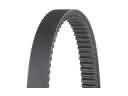
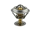
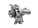
- Belts & Cooling Parts View More >
- Steering Parts View More >
- Suspension Parts View More >
- Emission Control & Exhaust Parts View More >
- A/C & Heating Parts View More >
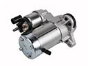
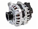
- Charging & Starting Parts View More >
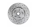
- Brakes Parts View More >
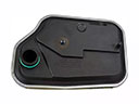
- Transmission Parts View More >


Why Buy Genuine Toyota Matrix Parts From ToyotaPartsNow.com
ToyotaPartsNow.com highlights the reliability of OEM Toyota Matrix parts right at your fingertips. Our skilled staff assists customers in selecting the right Toyota Matrix parts and provides expert help with any unique part requests. At ToyotaPartsNow.com, we make all Toyota Matrix parts available to you quickly and efficiently through our fast order and reliable ship process. Our service is designed to make finding the correct Toyota Matrix parts fast and easy whether you are an amateur or a professional. We offer access to a broad inventory that includes a wide range of Toyota years and variants. Affordable prices, quick processing and professional service are also our specialty to ensure your car remains in top condition with OEM Toyota Matrix parts. You can feel confident shopping with us because all Toyota Matrix parts, such as Headlights & Lighting you purchase from our store are of genuine quality and built to last.
The Toyota Matrix hatchback model underwent production from 2002 to 2014 as a compact vehicle that showcases engineering excellence and its specific design to reflect its automotive market importance. The Matrix belongs to Toyota's MC platform and provides front-wheel drive and four-wheel drive as choices which accommodate various driver needs. The initial generation Toyota Matrix equipped a 1.8 L I4 engine that could produce 180 hp and customers selected between five-speed or six-speed manual transmission options or four-speed automatic transmission to achieve performance and efficiency goals. The second generation brought a powerful 2.4 L I4 engine to boost both power outputs and driving performance. The vehicle possesses dimensions measuring 102.4 inches wheelbase with 171.3 inches length and 69.9 inches width and 61.0 inches height that enables both interior comfort and enhanced cargo storage. During its production time Toyota Matrix customers had three model options: base, XR and XRS that delivered comfortable driving with standard features including air-conditioning and CD player functions. The high priority placed on authentic Toyota Matrix components helps the vehicle maintain its operational reserves and dependability by using parts which match factory standards thus supporting the vehicle's strong reputation in the hatchback market.
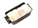
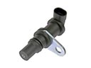
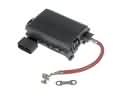
The Toyota Matrix is a reliable car; it might have a variety of problems with many systems. A common issue is when the Check Engine Light comes on because of a faulty oxygen sensor. This issue is something that can lead to bad mileage in the Toyota Matrix engine management. The other related issue is Check Engine Light which shows an EVAP system failure often caused by a faulty Toyota Matrix charcoal canister or loose gas cap. These two components are part of the engine's emissions system and may involve some parts replacement. Also, the Toyota Matrix can have a window regulator issue, as well as the bolts securing the front window glass loosening. This affects the operation of the windows and can cause more damage if not corrected. Fixing the Toyota Matrix window regulator to working condition is the goal of the repair process. On average, the Toyota Matrix may experience problems with engine management or even with the windows, which could require component replacement and service to restore proper function.
Toyota Matrix Parts and Q&A
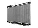
- Q: How to remove the radiator on Toyota Matrix?A:In order to take the radiator off, disconnected the negative battery terminal, loosened engine under covers, emptied the coolant and pulled off the front bumper assembly. Then take out the thermistor unit, disconnect the hoses, and take off the top radiator support. Lastly, unrun the cooling fan motor and take away the radiator assembly together with the fan shroud.
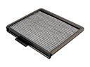
- Q: How to replace the Cabin Air Filter on Toyota Matrix?A:When you need to change the air refiner filter, open the glove box, screw it out and slide the damper. Unscrew the claws, dismount the filter cover and extract the filter. When contaminated, change it, making sure that the arrow on the new filter faces upwards.
- Q: How to install the alternator assembly on Toyota Matrix?A:In order to install the generator assembly, use a 8.4 Nm bolt to tighten the wire harness clamp bracket. Bolt the generator using two bolts (Bolt A 21 Nm, Bolt B 52 Nm). Install the terminal, wire harness and generator, fit the V-ribbed belt and engine under cover RH. Last but not least, apply the negative battery terminal.


