×
ToyotaParts- Hello
- Login or Register
- Quick Links
- Live Chat
- Track Order
- Parts Availability
- RMA
- Help Center
- Contact Us
- Shop for
- Toyota Parts
- Scion Parts
My Garage
My Account
Cart
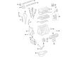
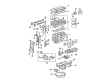
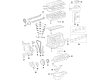
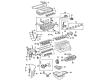
OEM Toyota Matrix Timing Chain
Engine Timing Chain- Select Vehicle by Model
- Select Vehicle by VIN
Select Vehicle by Model
orMake
Model
Year
Select Vehicle by VIN
For the most accurate results, select vehicle by your VIN (Vehicle Identification Number).
5 Timing Chains found


Toyota Matrix Timing Chain Part Number: 13506-0T020
$217.84 MSRP: $311.03You Save: $93.19 (30%)


Toyota Matrix Timing Chain Part Number: 13507-28010
$92.18 MSRP: $129.39You Save: $37.21 (29%)Ships in 1-2 Business Days


Toyota Matrix Timing Chain Part Number: 13506-0D010
$260.60 MSRP: $372.07You Save: $111.47 (30%)Ships in 1-3 Business Days

Toyota Matrix Timing Chain Part Number: 13506-0H011
$268.87 MSRP: $383.89You Save: $115.02 (30%)Ships in 1-2 Business Days


Toyota Matrix Timing Chain Part Number: 13506-88600
$272.71 MSRP: $389.37You Save: $116.66 (30%)Ships in 1-3 Business Days
Toyota Matrix Timing Chain
Choose genuine Timing Chain that pass strict quality control tests. You can trust the top quality and lasting durability. Shopping for OEM Timing Chain for your Toyota Matrix? Our website is your one-stop destination. We stock an extensive selection of genuine Toyota Matrix parts. The price is affordable so you can save more. It only takes minutes to browse and find the exact fit. Easily add to cart and check out fast. Our hassle-free return policy will keep you stress-free. We process orders quickly for swift delivery. Your parts will arrive faster, so you can get back on the road sooner.
Toyota Matrix Timing Chain Parts and Q&A
- Q: How to Replace a Timing Chain on Toyota Matrix?A:Start the timing chain replacement by eliminating the engine under cover RH while you empty the coolant and detach the front wheel RH. The next step requires removal of the cylinder head cover No.2 by unfastening the 2 nuts and 2 clips followed by removing the cover. Untwist the fan and generator V-belt tensioner by rotating it clockwise before you eliminate the belt and adjust the tensioner correctly. Set the vane pump assembly apart from the hose without removal followed by generator assembly removal. The procedure to uninstall the engine mounting insulator sub-assembly RH involves removing the PS oil pump reservoir followed by placing a wooden block between the jack and engine and then removing 4 bolts and 2 nuts. The procedure starts by removing 5 clamps from the engine wire and disconnecting 4 Ignition Coil connectors and unfastening a bolt and nut. Start by removing the 4 bolts of the ignition coil assembly along with its coils then disconnect ventilation hoses from the cylinder head cover. The cylinder head cover sub-assembly removal requires the removal of 9 bolts together with 2 seal washers, 2 nuts and 3 clamp brackets and the cover itself. Inspects No. 1 cylinder for TDC/compression position by making sure both the crankshaft pulley has "0" timing mark alignment and the points on the camshaft and VVT timing sprockets match. The crankshaft pulley requires SST 09960-10010 (09962-01000, 09963-01000) for removal before detaching the V-ribbed belt tensioner assembly. Start by removing the transverse engine mounting bracket together with the Water Pump assembly after unthreading the 3 bolts. The crank position sensor removal requires unfastening its 2 bolts followed by dismantling chain tensioner assembly No.1 through the removal of its 2 nuts. It is crucial to prevent crankshaft revolutions without using the chain tensioner. The timing chain or belt cover sub-assembly needs removal that requires undoing the 11 bolts and nuts followed by stud bolt extraction through a torx wrench socket (E8) before carefully prying the cover off. First remove the timing gear cover oil seal with a screwdriver before taking out the Crankshaft Position Sensor plate No.1 and chain tensioner slipper by removing the bolt. Pry the timing chain off the crankshaft timing gear while using screwdrivers but take precautions with a shop rag to protect the engine then rotate the crankshaft 1/4 revolutions to stop valves from touching pistons. Begin installation of the chain sub-assembly after setting No. 1 cylinder at TDC/compression while lining up camshaft timing sprockets and fitting the timing chain to the crankshaft timing sprocket with its yellow link at the timing mark. Follow instructions using SST 09223-22010 to attach the crankshaft timing sprocket after which you can place the timing chain on camshaft timing sprockets. The chain tensioner slipper requires installation with its bolt through which you must apply 19 Nm (194 kgf-cm, 14 ft. lbs.) torque. First attach the crankshaft position sensor plate with "F" mark indicating forward direction and afterward lubricate the new oil seal lips by applying MP grease before installing them with SST 09223-22010. The timing chain or belt cover sub-assembly requires removal of old packing and seal packing installation before securing the cover through specified torque values. Correctly position the chain tensioner hook along with a clean O-ring and install the cap. Mount the crank position sensor using both bolts. Add the three bolts to settle the transverse engine mounting bracket while proceeding to set the water pump assembly before tightening the V-ribbed belt tensioner assembly according to specifications. Use the set key to properly install the crankshaft pulley bolt with SST 09960-10010 before tightening it to 138 Nm (1,407 kgf-cm, 102 ft. lbs.). After turning the crankshaft to push the plunger against the slipper installed the cylinder head cover sub-assembly with proper torque values while using seal packing. Use 4 bolts to secure the ignition coil assembly before installing the engine wire through its bolt then adding the nut. The last maintenance steps involve installing the engine mounting insulator sub-assembly RH together with the generator assembly and the vane pump assembly and the cylinder head cover No.2 and then the front wheel RH followed by adding coolant before performing leak checks on engine coolant and oil.
- Q: How to install the timing chain on Toyota Matrix?A:A proper installation process for the 1ZZ-FE timing chain requires users to set the No. 1 cylinder at TDC/compression by aligning Camshaft timing gear marks while using a crankshaft pulley bolt to set the timing gear key to the oil pump point mark. Utilize Special Service Tool: 09223-22010 to properly install the crankshaft timing gear while positioning its key point with the fitting yellow mark facing the timing mark. Begin the installation of the chain onto camshaft timing gears by placing the yellow mark links straight against their timing fixtures. The chain tensioner slipper requires installation with a bolt mounted at 18.5 Nm (189 kgf-cm, 14 ft-lbf) torque before attaching the "F" marked crankshaft position sensor plate to face forward. A light coat of multi-purpose grease covers a new oil seal lip before using Special Service Tool: 09223-22010 to tap the oil seal into the timing chain cover until it reaches its edge while inspecting for foreign objects on the lip. Fill the timing chain cover cave with a continuous seal packing string (3.5 to 4.5 mm diameter) after you remove old packing materials from the surface. Install the cover with 10 bolts and 2 nuts while torquing Bolt A and nut A to 13 Nm (133 kgf-cm, 10 ft-lbf) and Bolt B to 18.5 Nm (189 kgf-cm, 14 ft-lbf). Install the stud bolt with a "TORX" socket wrench (E8) type and achieve a final torque value of 9.5 Nm (97 kgf-cm, 84 in-lbf). The chain tensioner assembly requires you to clean and add engine oil to its O-ring before installation with 2 nuts that should be torqued to 9.0 Nm (92 kgf-cm, 80 in-lbf) while ensuring the O-ring maintains its original position. Fix the crankshaft pulley with the pulley set key in position on the key groove before using Special Service Tools: 09960-10010, 09962-01000 and 09963-01000 to secure the crankshaft pulley bolt at 138 Nm (1,407 kgf-cm, 102 ft-lbf). Use the plunger knock pin hook to separate it and ensure the slipper receives plunger force which moves it inside the chain tensioner when needed. The procedure involves applying engine oil to the O-ring of the crankshaft position sensor and installing it with 2 bolts which need to be torqued to 9.0 Nm (92 kgf-cm, 80 in-lbf) before installing the Water Pump assembly. Proceed by installing the engine mounting bracket RH with 47 Nm (479 kgf-cm, 35 ft-lbf) torque then install the V-ribbed belt tensioner assembly by torquing the bolt to 69 Nm (704 kgf-cm, 51 ft-lbf) and the nut to 29 Nm (296 kgf-cm, 21 ft-lbf). Set the head cylinder by applying seal packing on specific points before installation with nine bolts, two seal washers, two nuts, torquing Bolt A to 11 Nm (112 kgf-cm, 8 ft-lbf) with nut A and Bolt B to 9.0 Nm (92 kgf-cm, 80 in-lbf). The Ignition Coil assembly receives 4 bolts applying a torque setting at 9.0 Nm (92 kgf-cm, 80 in-lbf) before installing two engine wires using 2 nuts fixed at 9.0 Nm (92 kgf-cm, 80 in-lbf). Subsequently, the ignition coil connectors must be connected. The process begins with installing the engine mounting insulator RH through 4 bolts alongside 2 nuts that require torquing to 52 Nm (530 kgf-cm, 38 ft-lbf) before installing the oil reservoir bracket No. 1 using 2 bolts torqued to 7.8 Nm (80 kgf-cm, 69 in-lbf). Proceed with the generator assembly installation followed by the vane pump assembly installation and then install the fan assembly as well as the generator V belt. The service should begin by adding engine coolant followed by connecting the battery negative terminal at 5.4 Nm (55 kgf-cm, 48 in-lbf) torque before inspecting both engine coolant and oil leaks. To finish the installation process install cylinder head cover No. 2 using 2 nuts and 2 clips torqued to 7.0 Nm (71 kgf-cm, 62 in-lbf) along with the front wheel RH that needs a torque setting of 103 Nm (1,050 kgf-cm, 76 ft-lbf).


Related Toyota Matrix Parts
 Toyota Matrix Engine Mount
 Toyota Matrix Oil Pan
 Toyota Matrix Valve Cover Gasket
 Toyota Matrix Camshaft
 Toyota Matrix Camshaft Bearing
 Toyota Matrix Crankshaft Thrust Washer
 Toyota Matrix Cylinder Head
 Toyota Matrix Dipstick
 Toyota Matrix Piston Ring Set
 Toyota Matrix Rocker Arm
 Toyota Matrix Rod Bearing
 Toyota Matrix Valve Stem Seal