×
ToyotaParts- Hello
- Login or Register
- Quick Links
- Live Chat
- Track Order
- Parts Availability
- RMA
- Help Center
- Contact Us
- Shop for
- Toyota Parts
- Scion Parts
My Garage
My Account
Cart
OEM 2008 Toyota Matrix Timing Chain
Engine Timing Chain- Select Vehicle by Model
- Select Vehicle by VIN
Select Vehicle by Model
orMake
Model
Year
Select Vehicle by VIN
For the most accurate results, select vehicle by your VIN (Vehicle Identification Number).
1 Timing Chain found


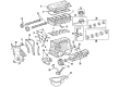
2008 Toyota Matrix Timing Chain
Part Number: 13506-0D010$260.60 MSRP: $372.07You Save: $111.47 (30%)Ships in 1-3 Business DaysProduct Specifications- Other Name: Chain Sub-Assembly; Engine Timing Chain
- Manufacturer Note: ENGINE NO.=5001001-9XXXXXX OR CXXXXXX
- Replaces: 13506-22030, 13506-0D020
- Part Name Code: 13506
- Item Weight: 1.20 Pounds
- Item Dimensions: 12.5 x 12.1 x 8.1 inches
- Condition: New
- Fitment Type: Direct Replacement
- SKU: 13506-0D010
- Warranty: This genuine part is guaranteed by Toyota's factory warranty.
2008 Toyota Matrix Timing Chain
Looking for affordable OEM 2008 Toyota Matrix Timing Chain? Explore our comprehensive catalogue of genuine 2008 Toyota Matrix Timing Chain. All our parts are covered by the manufacturer's warranty. Plus, our straightforward return policy and speedy delivery service ensure an unparalleled shopping experience. We look forward to your visit!
2008 Toyota Matrix Timing Chain Parts Q&A
- Q: How to remove the timing chain on 2008 Toyota Matrix?A: Begin timing chain removal on the 1ZZ-FE engine by removing the negative terminal from the battery followed by separating the front wheel right side with the removal of the engine under cover on the right side. Remove the cylinder head cover No. 2 by unfastening its two nuts and two clips. First drain the engine coolant before removing both the fan along with the generator V belt. You should dismantle the van pump unit while extracting the generator unit. Start by removing 2 bolts from the engine mounting insulator RH followed by bracket No. 1 from the oil reservoir then put a wooden block with a jack to support the engine and take out 4 bolts along with 2 nuts. To remove the ignition coil assembly disconnect the 4 ignition coil connectors, remove 2 nuts then separate the engine wire and take out 4 bolts. The cylinder head cover sub-assembly removal requires disconnecting ventilation hoses followed by removing 3 clamps from the engine wire and unfastening 9 bolts, 2 seal washers, 2 nuts with 3 clamp brackets. You can start the V-ribbed belt tensioner assembly removal process by undoing bolt and nut attachments, afterward raise and lower the motor to help remove bolts before fully taking out the engine mounting bracket RH with three bolt removals. Crank the engine until the No. 1 cylinder reaches TDC/compression position while ensuring camshaft timing gears are properly aligned. Then detach the water pump assembly before disconnecting the crankshaft position sensor through its 2 bolts. Service tools 09960-10010 09962-01000 09963-01000 enable complete removal of the crankshaft pulley bolt which then allows the lift of the crankshaft pulley. Open the chain tensioner assembly No.1 through using a wrench on two nuts except turning the crankshaft during the operation. The timing chain or belt cover sub-assembly removal begins with extracting ten bolts and two nuts before using a "TORX" socket wrench (E8) to remove the stud bolt and carefully prying the cover away without damaging contact surfaces. Use a screwdriver to remove the timing chain or belt cover oil seal before taking off the crankshaft position sensor plate No.1 then remove the chain tensioner slipper by uninstalling its bolt and finally use two screwdrivers to pull out the chain with the crankshaft timing gear while wrapping the engine in a shop rag or cloth before turning the crankshaft 1/4 revolution if rotating the camshafts without the chain on the gears to avoid piston contact with valves.
Related 2008 Toyota Matrix Parts
 2008 Toyota Matrix Engine Mount
 2008 Toyota Matrix Camshaft
 2008 Toyota Matrix Crankshaft Seal
 2008 Toyota Matrix Crankshaft Thrust Washer Set
 2008 Toyota Matrix Cylinder Head Gasket
 2008 Toyota Matrix Dipstick
 2008 Toyota Matrix Dipstick Tube
 2008 Toyota Matrix Exhaust Valve
 2008 Toyota Matrix Harmonic Balancer
 2008 Toyota Matrix Piston Ring Set
 2008 Toyota Matrix Rod Bearing
 2008 Toyota Matrix Variable Timing Sprocket