×
ToyotaParts- Hello
- Login or Register
- Quick Links
- Live Chat
- Track Order
- Parts Availability
- RMA
- Help Center
- Contact Us
- Shop for
- Toyota Parts
- Scion Parts
My Garage
My Account
Cart
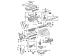
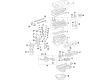
OEM Toyota Matrix Camshaft
Cam- Select Vehicle by Model
- Select Vehicle by VIN
Select Vehicle by Model
orMake
Model
Year
Select Vehicle by VIN
For the most accurate results, select vehicle by your VIN (Vehicle Identification Number).
8 Camshafts found


Toyota Matrix Exhaust Camshaft Part Number: 13502-29015
$352.07 MSRP: $515.96You Save: $163.89 (32%)Ships in 1-3 Business Days


Toyota Matrix Intake Camshaft Part Number: 13501-29025
$357.40 MSRP: $523.77You Save: $166.37 (32%)Ships in 1-3 Business Days


Toyota Matrix Camshaft Part Number: 13501-28060
$343.78 MSRP: $503.81You Save: $160.03 (32%)

Toyota Matrix Camshaft Part Number: 13501-22062
$340.75 MSRP: $486.51You Save: $145.76 (30%)Ships in 1-3 Business Days
Toyota Matrix Intake Camshaft Part Number: 13501-37040
$277.37 MSRP: $396.03You Save: $118.66 (30%)Ships in 1-2 Business DaysToyota Matrix Exhaust Camshaft Part Number: 13502-37050
$293.45 MSRP: $418.98You Save: $125.53 (30%)Ships in 1-2 Business Days
Toyota Matrix Camshaft Part Number: 13502-28030
$323.51 MSRP: $461.90You Save: $138.39 (30%)Ships in 1-3 Business Days


Toyota Matrix Camshaft Part Number: 13502-22011
$322.11 MSRP: $459.90You Save: $137.79 (30%)
Toyota Matrix Camshaft
Choose genuine Camshaft that pass strict quality control tests. You can trust the top quality and lasting durability. Shopping for OEM Camshaft for your Toyota Matrix? Our website is your one-stop destination. We stock an extensive selection of genuine Toyota Matrix parts. The price is affordable so you can save more. It only takes minutes to browse and find the exact fit. Easily add to cart and check out fast. Our hassle-free return policy will keep you stress-free. We process orders quickly for swift delivery. Your parts will arrive faster, so you can get back on the road sooner.
Toyota Matrix Camshaft Parts and Q&A
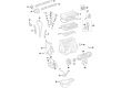
- Q: How to remove the camshaft on Toyota Matrix?A:The first step of removing a 2AZ-FE engine camshaft requires the engineer to remove the engine under cover RH followed by the No. 1 engine cover sub-assembly. The essential step involves removing Ignition Coil assembly along with the Spark Plug. The removal process begins with detaching the two hoses for ventilation and then separating the two wire harness brackets before you can remove eight bolts, two nuts, and the two ventilation hose. Reach TDC/compression position of the No. 1 cylinder through crankshaft pulley rotation until the pulley groove connects with the timing mark "0" on the Timing Chain cover, while the camshaft timing gear and sprocket marks must match up with the No. 1 and No. 2 bearing caps; a single crankshaft pulley rotation is needed to achieve proper alignment. The technician marks the chain at the same position as the timing marks appear. First remove the No. 1 chain tensioner assembly after which you can loosen the No. 2 camshaft timing gear or sprocket by gripping the No. 2 camshaft with a wrench. The correct process to remove the No. 2 camshaft entails uniformly loosening and removing the 10 bearing cap bolts according to a specified sequence before extracting the 5 bearing caps while securely holding the No. 2 camshaft to detach the camshaft timing sprocket set bolt and sprocket with its timing chain. Start by uniformly removing the 10 bearing cap bolts and extracting all 5 bearing caps to retrieve the camshaft and camshaft timing gear assembly when holding the timing chain with a string for securement to the crankshaft sprocket. Ensure that no objects fall within the timing chain cover area. You must clamp the camshaft inside a vise during removal to stop movement while using vinyl tape to cover all oil paths besides the advance side path then using 150 kPa (1.5 kgf/cm2,22psi) of air pressure to operate the opened path by turning the camshaft timing gear assembly clockwise. Place a cloth across the paths before the operation to stop oil from splashing out. There are specific instructions for removing the flange bolt of the camshaft timing gear which mandates the preservation of all other 4 bolts while conducting camshaft timing gear reuse necessitates prior unlocking of straight pin lock mechanisms.
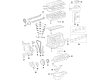
- Q: How to install the camshaft on Toyota Matrix?A:Before installing the camshaft start by setting up the camshaft timing gear with the camshaft but keep the straight pin away from the key groove while rotating the gear to the left while using gentle pressure to guide it toward the pin position that leads to no movement toward the retard angle side. Confirm that there is no gap remaining between the gear and camshaft after installation before securing the bolt to 54 Nm (551 kgf-cm, 40 ft-lbf). Tighten the fringe bolt to a torque of 54 Nm which equates to 551 kgf-cm or 40 ft-lbf after making sure the gear fringe maintains enough contact with the camshaft. Check that the camshaft timing gear can move towards the retard angle position before fixing it into the most retarded position. After placing the Timing Chain on the camshaft timing gear ensure that paint marks and numbers show proper sequence while tightening bolts to 13 Nm (133 kgf-cm, 10 ft-lbf). Place the No. 2 camshaft on its cylinder head with the paint mark of the timing chain matching the timing mark before tightening the camshaft timing gear set bolt temporarily. Verify the sequence before applying torque of 13 Nm (133 kgf-cm, 10 ft-lbf). Apply bearing cap No. 1 with a torque of 23 Nm (235 kgf-cm, 17 ft-lbf) then maintain hold of the camshaft during the tightening procedure of the timing gear set bolt to 54 Nm (551 kgf-cm, 40 ft-lbf) making sure to protect the valve lifter. Veryficate matching positioning of the two point marks on the timing chain cover surface and also verify that the timing marks align with their respective colored links on the timing chain which should align with the timing mark number "0" on the chain cover as the groove. Position the chain tensioner correctly by cleaning the O-ring and positioning the hook before applying small amounts of engine oil to the O-ring and tightening two nuts to 9.0 Nm while avoiding twisting the O-ring. The crankshaft rotation must move backwards to remove the plunger knock pin from the hook before turning in the clockwise direction to verify plunger extension against the slipper. Use a screwdriver to push the slipper if the plunger does not extend. The procedure ends with adjusting the valve clearance and installing the cylinder head cover sub-assembly before installing the Ignition Coil assembly and connecting the battery negative terminal at 5.4 Nm (55 kgf-cm, 48 in-lbf). An engine oil leakage check is performed before installing cylinder head cover No. 2 and the engine under cover RH.


Related Toyota Matrix Parts
 Toyota Matrix Oil Filter
 Toyota Matrix Engine Cover
 Toyota Matrix Oil Pan
 Toyota Matrix Camshaft Bearing
 Toyota Matrix Cylinder Head Gasket
 Toyota Matrix Dipstick Tube
 Toyota Matrix Exhaust Valve
 Toyota Matrix Harmonic Balancer
 Toyota Matrix Intake Valve
 Toyota Matrix Piston
 Toyota Matrix Piston Ring Set
 Toyota Matrix Valve Stem Seal