×
ToyotaParts- Hello
- Login or Register
- Quick Links
- Live Chat
- Track Order
- Parts Availability
- RMA
- Help Center
- Contact Us
- Shop for
- Toyota Parts
- Scion Parts
My Garage
My Account
Cart
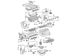
OEM 2003 Toyota Matrix Camshaft
Cam- Select Vehicle by Model
- Select Vehicle by VIN
Select Vehicle by Model
orMake
Model
Year
Select Vehicle by VIN
For the most accurate results, select vehicle by your VIN (Vehicle Identification Number).
4 Camshafts found


2003 Toyota Matrix Intake Camshaft
Part Number: 13501-29025$352.07 MSRP: $515.95You Save: $163.88 (32%)Ships in 1-3 Business DaysProduct Specifications- Other Name: Camshaft Sub-Assembly; Camshaft
- Replaces: 13501-29015
- Part Name Code: 13511
- Item Weight: 8.00 Pounds
- Item Dimensions: 20.9 x 3.3 x 2.9 inches
- Condition: New
- Fitment Type: Direct Replacement
- SKU: 13501-29025
- Warranty: This genuine part is guaranteed by Toyota's factory warranty.


2003 Toyota Matrix Exhaust Camshaft
Part Number: 13502-29015$346.84 MSRP: $508.31You Save: $161.47 (32%)Ships in 1-3 Business DaysProduct Specifications- Other Name: Camshaft Sub-Assembly; Camshaft
- Part Name Code: 13512
- Item Weight: 4.20 Pounds
- Item Dimensions: 21.3 x 3.3 x 2.8 inches
- Condition: New
- Fitment Type: Direct Replacement
- SKU: 13502-29015
- Warranty: This genuine part is guaranteed by Toyota's factory warranty.


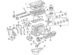
2003 Toyota Matrix Camshaft
Part Number: 13502-22011$317.33 MSRP: $453.09You Save: $135.76 (30%)Ships in 1-3 Business DaysProduct Specifications- Other Name: Camshaft Sub-Assembly
- Manufacturer Note: (J)
- Replaces: 13502-0D010, 13502-22010
- Part Name Code: 13512
- Item Weight: 3.70 Pounds
- Item Dimensions: 21.1 x 3.3 x 2.8 inches
- Condition: New
- Fitment Type: Direct Replacement
- SKU: 13502-22011
- Warranty: This genuine part is guaranteed by Toyota's factory warranty.

2003 Toyota Matrix Camshaft
Part Number: 13501-22062$335.62 MSRP: $479.20You Save: $143.58 (30%)Ships in 1-3 Business DaysProduct Specifications- Other Name: Camshaft Sub-Assembly
- Replaces: 13501-22060, 13501-22061, 13501-0D030
- Item Weight: 4.70 Pounds
- Item Dimensions: 21.1 x 3.4 x 2.9 inches
- Condition: New
- SKU: 13501-22062
- Warranty: This genuine part is guaranteed by Toyota's factory warranty.
2003 Toyota Matrix Camshaft
Looking for affordable OEM 2003 Toyota Matrix Camshaft? Explore our comprehensive catalogue of genuine 2003 Toyota Matrix Camshaft. All our parts are covered by the manufacturer's warranty. Plus, our straightforward return policy and speedy delivery service ensure an unparalleled shopping experience. We look forward to your visit!
2003 Toyota Matrix Camshaft Parts Q&A
- Q: How to Replace a Camshaft on 2003 Toyota Matrix?A: The camshaft replacement process starts by removing the engine under cover RH and Proceed to remove the cylinder head cover No. 2 through a combination of three bolts and a single nut and the cover piece. The ignition coil assembly can be removed after you disconnect 4 connectors attached to 4 bolts and unfasten these bolts. The fuel hose clamp and 2 PCV hoses must be removed from the cylinder head cover before taking out 2 nuts and 1 bolt along with the No. 3 ventilation hose and the No. 1 ventilation pipe and ventilation No. 1 tube and gasket. The technician removes 8 bolts together with the wire harness protector and cylinder head cover and its gasket before extracting the O-ring from the cylinder head cover. Disconnect the engine wire harness before removing the bolt that has the wiring harness clamp bracket attached. Unfasten the two suction hose sub-assembly retaining nuts and disconnect it. First loosen the V-belt that connects the fan and generator through clockwise movement of the tensioner before removing the belt. Each step of the TDC/compression configuration for the No. 1 cylinder requires that the crankshaft pulley channel align with the timing mark "0" on the timing chain cover where the camshaft timing sprocket and VVT timing sprocket point marks should match perfectly. Any misalignment requires a one-click rotation of the crankshaft. Use a jack with wooden block placed under the engine to uninstall the engine mounting insulator sub-assembly RH along with removal of 5 bolts and 2 nuts. Take appropriate precautions when uninstalling the V-ribbed belt tensioner assembly with a jack in place. The following steps should be followed when removing the camshaft: start by keeping the crankshaft stable without the tensioner then move on to orienting the No. 1 cylinder at TDC/compression while placing matching marks on the timing chain and camshaft timing sprockets before taking out 2 nuts and the tensioner followed by applying a wrench to the camshaft and lastly unscrewing the camshaft timing gear set bolt while guarding against touching the valve lifter. Loosen the specified sequence of camshaft bearing cap bolts on No. 2 camshaft and remove the caps followed by camshaft timing gear and camshaft removal while holding the timing chain and securing it with a string to prevent falling debris inside the timing chain cover. A vice must hold the camshaft to verify the timing gear locks into place. Release the lock pin before applying vinyl tape to block the paths along the cam journal, but leave one of the advance side paths open with a rubber stopper. Check the camshaft timing gear assembly by removing its advance and retard side path tapes before applying air pressure that will turn the gear toward the advance timing position with reducing pressure in the retard side path. You should check for free movement without resistance when rotating the camshaft timing gear assembly manually while ensuring it holds its most retarded position. After gripping the camshaft in a vice users need to tape the oil paths then break through the tapes after which they should apply air pressure to verify the gear moves in the timing advance direction. The technician can remove the fringe bolt on the camshaft timing gear assembly yet leave the remaining 4 bolts intact. The cam timing control valve housing removal requires three bolts and two nuts to be taken out before proceeding to remove valve rocker shaft sub-assembly No. 1 and No. 2 by uninstalling their bolts and rocker arms. During the evaluation process of valve rocker arms, technicians should use vinyl tape to cover oil paths and align each oil path between the rocker arm and rocker arm shaft before applying air pressure for piston movement checks. Thread the cylinder head with valve rocker shaft sub-assemblies No. 2 and No. 1 followed by securing the bolts to achieve 7.5 Nm torque. The cam timing control valve housing needs new gasket application before 3 bolts and 2 nuts secure it at 9.0 Nm torque. To install the camshaft timing gear assembly fit it properly to the camshaft while preventing friction between the gear fringe and the camshaft before tightening the fringe bolt to 54 Nm. To install the camshaft you must place the timing chain next to the camshaft timing gear then tighten bolts following the specified sequence to 19 Nm condition while maintaining painted chain links in proper alignment with timing marks. Set the bolt with medium torque and securely position the camshaft before torquing the bolt that supports the camshaft timing gear at 54 Nm without harming the valve lifter. Before installation, clean the O-ring of the chain tensioner and apply engine oil before tightening it at 9.0 Nm torque. Position the V-ribbed belt tensioner assembly correctly before fixing the nut to 29 Nm and the bolt to 100 Nm. Affix the right-hand engine mounting insulator sub-assembly through 5 bolts and 2 nuts at 52 Nm torque. The complete cylinder head cover assembly installation requires removal of former packing materials followed by the application of new seal packing (Part No. 08826-00080 or equivalent) on two positions before installing the cylinder head cover gasket with spark plug tube gasket and a new O-ring. Secure the cylinder head cover and wire harness protector with 8 bolts at 10 Nm as the first step while connecting the 2 PCV hoses and setting the new gasket with the No. 1 ventilation pipe using 2 nuts and a bolt at specified torques. To complete the installation, first connect the No. 3 ventilation hose then install the suction hose sub-assembly at 9.8 Nm while putting the wire harness clamp at 10 Nm followed by inserting the ignition coil assembly at 9.0 Nm and completing with cylinder head cover No. 2 at 7.0 Nm before conducting an inspection for oil leakage.
Related 2003 Toyota Matrix Parts
 2003 Toyota Matrix Oil Filter
 2003 Toyota Matrix Timing Chain
 2003 Toyota Matrix Engine Mount
 2003 Toyota Matrix Crankshaft Pulley
 2003 Toyota Matrix Cylinder Head
 2003 Toyota Matrix Dipstick
 2003 Toyota Matrix Harmonic Balancer
 2003 Toyota Matrix Intake Valve
 2003 Toyota Matrix Oil Pump Gasket
 2003 Toyota Matrix Timing Cover
 2003 Toyota Matrix Valve Stem Seal
 2003 Toyota Matrix Variable Timing Sprocket