×
ToyotaParts- Hello
- Login or Register
- Quick Links
- Live Chat
- Track Order
- Parts Availability
- RMA
- Help Center
- Contact Us
- Shop for
- Toyota Parts
- Scion Parts
My Garage
My Account
Cart
OEM 2003 Toyota Matrix Timing Chain
Engine Timing Chain- Select Vehicle by Model
- Select Vehicle by VIN
Select Vehicle by Model
orMake
Model
Year
Select Vehicle by VIN
For the most accurate results, select vehicle by your VIN (Vehicle Identification Number).
2 Timing Chains found


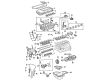
2003 Toyota Matrix Timing Chain
Part Number: 13506-88600$272.71 MSRP: $389.37You Save: $116.66 (30%)Ships in 1-3 Business DaysProduct Specifications- Other Name: Chain Sub-Assembly
- Part Name Code: 13506
- Item Weight: 1.30 Pounds
- Item Dimensions: 6.3 x 3.2 x 1.3 inches
- Condition: New
- Fitment Type: Direct Replacement
- SKU: 13506-88600
- Warranty: This genuine part is guaranteed by Toyota's factory warranty.


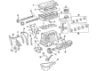
2003 Toyota Matrix Timing Chain
Part Number: 13506-0D010$260.60 MSRP: $372.07You Save: $111.47 (30%)Ships in 1-3 Business DaysProduct Specifications- Other Name: Chain Sub-Assembly; Engine Timing Chain
- Manufacturer Note: ENGINE NO.=5001001-9XXXXXX OR CXXXXXX
- Replaces: 13506-22030, 13506-0D020
- Part Name Code: 13506
- Item Weight: 1.20 Pounds
- Item Dimensions: 12.5 x 12.1 x 8.1 inches
- Condition: New
- Fitment Type: Direct Replacement
- SKU: 13506-0D010
- Warranty: This genuine part is guaranteed by Toyota's factory warranty.
2003 Toyota Matrix Timing Chain
Looking for affordable OEM 2003 Toyota Matrix Timing Chain? Explore our comprehensive catalogue of genuine 2003 Toyota Matrix Timing Chain. All our parts are covered by the manufacturer's warranty. Plus, our straightforward return policy and speedy delivery service ensure an unparalleled shopping experience. We look forward to your visit!
2003 Toyota Matrix Timing Chain Parts Q&A
- Q: How to Replace a Timing Chain on 2003 Toyota Matrix?A: Replace the timing chain by first stripping off both engine under cover RH and draining off coolant. Remove cylinder head cover No. 2 by uninstalling the 3 bolts and existing nut before removing the cover. The engine wire harness must be disconnected before the bolt and wiring harness clamp bracket can be removed. The removal of the suction hose sub-assembly starts with the removal of its two nuts together with the hose itself. Using a drive belt tensioner tool to turn clockwise you can first loosen V-belts between the fan and generator before you remove both generator bracket No. 1 along with the generator assembly. The service process starts with disconnecting the ignition coil connectors along with the oil control valve and crankshaft position sensor connector and finally removing the bolt and nut for the earth. The procedure to remove the cylinder head cover sub-assembly includes disconnecting the fuel hose clamp and 2 PCV hoses followed by removing 2 nuts, a bolt and No. 3 ventilation hose before removing 8 bolts, wire harness protector and cylinder head cover and its gasket. Strapping a jack beneath the engine while placing a wooden block between it and the jack enables removal of the 5 bolts and 2 nuts from the engine mounting insulator sub-assembly RH and cylinder head cover through their ordered sequence. Use the crankshaft pulley to set No. 1 cylinder at TDC/compression through alignment of its timing groove with "0" while ensuring the camshaft timing sprocket and VVT timing sprocket point marks match. Detach each of the components including the V-ribbed belt tensioner assembly and crankshaft pulley using Special Service Tools: 09213-70011 (09213-70020) and 09330-00021 as well as the water pump pulley using Special Service Tool: 09960-10010. After uninstalling the water pump assembly through 6 bolts removal you must separate the transverse engine mounting bracket after 4 bolt removal and disconnect the compressor with magnetic clutch by deleting the hoses. Use a torx wrench screw (E8) to delete the timing chain or belt cover sub-assembly and chain tensioner assembly No. 1 with its 2 nuts. The technician must replace the timing gear cover oil seal and crankshaft position sensor plate No. 1 together with chain tensioner slipper and chain vibration damper No. 1. Dismantle the timing chain together with the crankshaft timing gear while using screwdrivers but maintain the engine with a shop rag to prevent damage to the valves. Installation of the chain sub-assembly requires setting No. 1 cylinder to TDC/compression position followed by sprocket point mark alignment and placement of the timing chain on the crankshaft timing sprocket where the yellow mark link should be aligned. Special Service Tool 09223-22010 should be used for sprocket and timing chain installation on camshaft timing sprockets. Install and torque the chain vibration damper No. 1 along with the chain tensioner slipper according to manufacturer specifications. Environmental Service Tool: 09223-22010 to perform a new oil seal install by tapping in direction while the crankshaft position sensor plate number one should receive facing forward orientation with "F" marking visible and receive an MP grease application on its oil sealing lip. The timing chain cover surfaces should be cleaned after which you must apply two types of seal packing (Part No. 08826-00100 or equivalent + Part No. 08826-00080 or equivalent) onto the gasket sites before tightening the timing chain cover with the correct torque. Set the chain tensioner assembly No. 1 with correctly positioned hook while also cleaning the O-ring before assembly. Safely install the crankshaft pulley by aligning it properly then torque it according to specifications while also installing the crank position sensor and compressor and magnetic clutch. The service team should install the water pump assembly with its new O-ring by performing torque specifications followed by the transverse engine mounting bracket and water pump pulley. Add V-ribbed belt tensioner assembly together with an engine mounting insulator sub-assembly RH and cylinder head cover sub-assembly alongside its gaskets and seal packing and an ignition coil assembly and generator assembly and generator bracket No. 1 and suction hose sub-assembly and wire harness clamp and cylinder head cover No. 2 after adding coolant to the system and inspecting for all possible leaks.
Related 2003 Toyota Matrix Parts
 2003 Toyota Matrix Engine Mount
 2003 Toyota Matrix Camshaft
 2003 Toyota Matrix Crankshaft Seal
 2003 Toyota Matrix Crankshaft Thrust Washer Set
 2003 Toyota Matrix Dipstick
 2003 Toyota Matrix Exhaust Valve
 2003 Toyota Matrix Harmonic Balancer
 2003 Toyota Matrix Piston Ring Set
 2003 Toyota Matrix Rod Bearing
 2003 Toyota Matrix Spool Valve
 2003 Toyota Matrix Timing Cover Gasket
 2003 Toyota Matrix Variable Timing Sprocket