×
ToyotaParts- Hello
- Login or Register
- Quick Links
- Live Chat
- Track Order
- Parts Availability
- RMA
- Help Center
- Contact Us
- Shop for
- Toyota Parts
- Scion Parts
My Garage
My Account
Cart
OEM 2004 Toyota Matrix Timing Chain
Engine Timing Chain- Select Vehicle by Model
- Select Vehicle by VIN
Select Vehicle by Model
orMake
Model
Year
Select Vehicle by VIN
For the most accurate results, select vehicle by your VIN (Vehicle Identification Number).
2 Timing Chains found


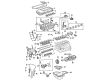
2004 Toyota Matrix Timing Chain
Part Number: 13506-88600$272.71 MSRP: $389.37You Save: $116.66 (30%)Ships in 1-3 Business DaysProduct Specifications- Other Name: Chain Sub-Assembly
- Part Name Code: 13506
- Item Weight: 1.30 Pounds
- Item Dimensions: 6.3 x 3.2 x 1.3 inches
- Condition: New
- Fitment Type: Direct Replacement
- SKU: 13506-88600
- Warranty: This genuine part is guaranteed by Toyota's factory warranty.


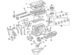
2004 Toyota Matrix Timing Chain
Part Number: 13506-0D010$260.60 MSRP: $372.07You Save: $111.47 (30%)Ships in 1-3 Business DaysProduct Specifications- Other Name: Chain Sub-Assembly; Engine Timing Chain
- Manufacturer Note: ENGINE NO.=5001001-9XXXXXX OR CXXXXXX
- Replaces: 13506-22030, 13506-0D020
- Part Name Code: 13506
- Item Weight: 1.20 Pounds
- Item Dimensions: 12.5 x 12.1 x 8.1 inches
- Condition: New
- Fitment Type: Direct Replacement
- SKU: 13506-0D010
- Warranty: This genuine part is guaranteed by Toyota's factory warranty.
2004 Toyota Matrix Timing Chain
Looking for affordable OEM 2004 Toyota Matrix Timing Chain? Explore our comprehensive catalogue of genuine 2004 Toyota Matrix Timing Chain. All our parts are covered by the manufacturer's warranty. Plus, our straightforward return policy and speedy delivery service ensure an unparalleled shopping experience. We look forward to your visit!
2004 Toyota Matrix Timing Chain Parts Q&A
- Q: How to replace the timing chain on 2004 Toyota Matrix?A: Start the timing chain replacement process by clearing away engine under cover RH and draining coolant and then removing the front wheel RH. The following step involves the removal of cylinder head cover No.2 through its 2 nuts and 2 clips before you extract the cover. Turn the V-ribbed belt tensioner clockwise to loosen it before removing both fan and generator V-belts. After fan and generator V-belt service replace the tensioner to its starting position. Users must separate the vane pump assembly while keeping the hose connected prior to removing the generator assembly alongside the engine mounting insulator sub-assembly RH. The PS oil pump reservoir requires moving aside before using a jack with wooden block to support the engine during the bolt and nut removal process. The engine wire requires removing 5 clamps and disconnecting 4 ignition coil connectors and unbolted the wire using nut and bolt attachment. Tear the ignition coil assembly apart by unfastening 4 bolts and extracting 4 ignition coils followed by disconnecting both ventilation hoses from the cylinder head cover. The process involves 9 bolts, 2 seal washers along with 2 nuts and 3 clamp brackets for removing the cylinder head cover sub-assembly. Alignment of crankshaft pulley's timing mark "0" with position "TDC/compression" must occur while the camshaft timing sprocket point marks should match with VVT timing sprocket point marks. Special Service Tool: 09960-10010 (09962-01000, 09963-01000) should be used to take off the crankshaft pulley bolt and pulley. The service technician must remove the V-ribbed belt tensioner assembly, water pump assembly, transverse engine mounting bracket with three bolts, crank position sensor with two bolts, chain tensioner assembly No.1 with two nuts, and timing chain or belt cover sub-assembly along with eleven bolts and nuts while using a torx wrench socket (E8) for stud bolt removal and carefully prying the cover open. The engine requires protection through a shop rag when removing the timing gear cover oil seal with a screwdriver and crankshaft position sensor plate No.1 and chain tensioner slipper by removing the bolt and the chain sub-assembly by prying it off with screwdrivers. Engine professionals should begin installation of the new chain sub-assembly by positioning No. 1 cylinder at TDC/compression and then aligning the camshaft sprockets before placing the chain on the crankshaft timing sprocket with the yellow link situated at the timing mark. Special Service Tool 09223-22010 allows installation of the crankshaft timing sprocket followed by positioning the timing chain over camshaft timing sprockets. Place the chain tensioner slipper in position using a bolt while tightening it to 19 Nm (194 kgf-cm, 14 ft. lbs.) and install the "F" mark facing forward on the crankshaft position sensor plate. The installation of new oil seals requires application of MP grease to their lip followed by tapping with Special Service Tool: 09223-22010 until the seal fully reaches the timing chain cover edge. Install the 11 bolts on the timing chain or belt cover sub-assembly while using seal packing of equivalent Water pump part No. 08826-00100 or Other part No. 08826-00080 following proper torque specifications. Participants should install Chain Tensioner Assembly No.1 by adding engine oil to the tensioner along with 2 nuts following proper installation of the hook and O-ring cleaning process. Montage the crank position sensor through two bolts alongside the transverse engine mounting with three bolts and water pump assembly and V-ribbed belt tensioner assembly according to specified torque values. Check the tensioner operation before installing the crankshaft pulley bolt with Special Service Tool: 09960-10010 by aligning the pulley set key into the key groove. The installation process includes placing the cylinder head cover sub-assembly with precise seal packing and order of parts as ignition coil assembly followed by engine wire and engine mounting insulator sub-assembly RH along with generator assembly vane pump assembly then cylinder head cover No.2. First reconnect the front wheel on the right side of the vehicle then add coolant before checking for leaks in both engine coolant and oil systems.
Related 2004 Toyota Matrix Parts
 2004 Toyota Matrix Engine Mount
 2004 Toyota Matrix Camshaft
 2004 Toyota Matrix Crankshaft Seal
 2004 Toyota Matrix Crankshaft Thrust Washer Set
 2004 Toyota Matrix Dipstick
 2004 Toyota Matrix Exhaust Valve
 2004 Toyota Matrix Harmonic Balancer
 2004 Toyota Matrix Piston Ring Set
 2004 Toyota Matrix Rod Bearing
 2004 Toyota Matrix Spool Valve
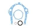 2004 Toyota Matrix Timing Cover Gasket
 2004 Toyota Matrix Variable Timing Sprocket