×
ToyotaParts- Hello
- Login or Register
- Quick Links
- Live Chat
- Track Order
- Parts Availability
- RMA
- Help Center
- Contact Us
- Shop for
- Toyota Parts
- Scion Parts
My Garage
My Account
Cart
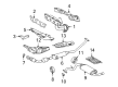
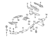
OEM Toyota Matrix Exhaust Manifold
Engine Exhaust Manifold- Select Vehicle by Model
- Select Vehicle by VIN
Select Vehicle by Model
orMake
Model
Year
Select Vehicle by VIN
For the most accurate results, select vehicle by your VIN (Vehicle Identification Number).
7 Exhaust Manifolds found


Toyota Matrix Exhaust Manifold Part Number: 17141-0T040
$251.98 MSRP: $359.77You Save: $107.79 (30%)Ships in 1-3 Business Days

Toyota Matrix Exhaust Manifold Part Number: 17104-22110
$570.21 MSRP: $835.66You Save: $265.45 (32%)Ships in 1-3 Business Days

Toyota Matrix Exhaust Manifold Part Number: 17104-22100
$217.84 MSRP: $311.03You Save: $93.19 (30%)Ships in 1-3 Business DaysToyota Matrix Exhaust Manifold Part Number: 17141-0T200
$198.50 MSRP: $283.42You Save: $84.92 (30%)Ships in 1-3 Business Days
Toyota Matrix Exhaust Manifold Part Number: 25051-28350
$603.01 MSRP: $751.56You Save: $148.55 (20%)Ships in 1-2 Business Days

Toyota Matrix Exhaust Manifold Part Number: 17140-88602

Toyota Matrix Exhaust Manifold Part Number: 17141-88H00
Toyota Matrix Exhaust Manifold
Choose genuine Exhaust Manifold that pass strict quality control tests. You can trust the top quality and lasting durability. Shopping for OEM Exhaust Manifold for your Toyota Matrix? Our website is your one-stop destination. We stock an extensive selection of genuine Toyota Matrix parts. The price is affordable so you can save more. It only takes minutes to browse and find the exact fit. Easily add to cart and check out fast. Our hassle-free return policy will keep you stress-free. We process orders quickly for swift delivery. Your parts will arrive faster, so you can get back on the road sooner.
Toyota Matrix Exhaust Manifold Parts and Q&A
- Q: How to install the exhaust manifold on Toyota Matrix?A:Start the exhaust manifold assembly by installing the No. 1 manifold converter insulator through 4 bolts which need proper torque of 12 Nm (122 kgf-cm, 9 ft-lbf). Next install two bolts for the No. 2 exhaust manifold heat insulator while torquing them to 12 Nm (122 kgf-cm, 9 ft-lbf). Mount the exhaust manifold converter sub-assembly with the new gasket and torque its 5 nuts to 37 Nm (377 kgf-cm, 27 ft-lbf). The installation process starts with a bolt and nut on the No. 2 manifold stay while torquing to 44 Nm (449 kgf-cm, 33 ft-lbf); next is the manifold stay with another bolt and nut that receives the same torque of 44 Nm (449 kgf-cm, 33 ft-lbf). After installing the air fuel ratio sensor you should place the No. 1 exhaust manifold heat insulator with 4 bolts using a torque of 12 Nm (122 kgf-cm, 9 ft-lbf). Inspect the compression spring length in the front Exhaust Pipe assembly using a vernier caliper because replacement is necessary when the measurement falls short of minimum specifications. Clean the converter section of the exhaust manifold with a brush then install the new gasket correctly while avoiding damage before adding 2 springs along with 2 bolts and torquing them to 43 Nm (440 kgf-cm, 32 ft-lbf) while connecting 2WD heated oxygen sensor cables. You must measure the compression springs and gaskets needed for the center exhaust pipe assembly before installing 4 bolts and 2 compression springs which should be tightened to 43 Nm (440 kgf-cm, 32 ft-lbf) after connecting it to exhaust pipe supports following suspension design. The center exhaust pipe assembly of 4WD systems must connect to 3 exhaust pipe supports before installation. Installation of the generator assembly and V-ribbed belt needs to follow engine under cover RH installation before reconnecting the cable to the negative battery terminal while some systems require system initialization when using the negative cable. Check for exhaust gas leakage as the last step.
- Q: How to remove the exhaust manifold on Toyota Matrix?A:The first step to remove the exhaust manifold should start with unconnecting the negative battery cable while acknowledging that certain systems might need post-reconnection initialization. The first task involves engine under cover RH removal followed by V-ribbed belt extraction. First remove the generator assembly from the system. The center Exhaust Pipe assembly on 2WD requires removing 4 bolts and 2 compression springs to detach from 2 exhaust pipe supports for torsion beam or 3 supports for double wishbone suspension systems. Afterwards remove its 2 gaskets. A 4WD version requires disconnecting the heated oxygen sensor connector and using a wrench to remove 4 bolts with two compression springs before separating it from three exhaust pipe supports to finally discard the two gaskets. First detach the heated oxygen sensor connector for 2WD then remove the 2 bolts, 2 compression springs and front exhaust pipe assembly before obtaining the exhaust manifold gasket. Clear away the No. 1 exhaust manifold heat insulator after removing its 4 bolts followed by the air fuel ratio sensor removal. Start by removing the manifold stay after disconnecting its bolt and nut before moving to the No. 2 manifold stay. You need to take out the 5 nuts with the gasket to separate the exhaust manifold converter sub-assembly. Use two bolts to remove the No. 2 exhaust manifold heat insulator before you finish with the removal of the No. 1 manifold converter insulator through removing its 4 bolts.


Related Toyota Matrix Parts
 Toyota Matrix Catalytic Converter
 Toyota Matrix Exhaust Heat Shield
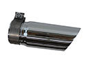 Toyota Matrix Exhaust Tip
 Toyota Matrix Muffler
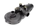 Toyota Matrix PCV Valve
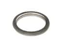 Toyota Matrix Exhaust Flange Gasket
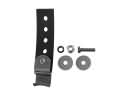 Toyota Matrix Exhaust Hanger
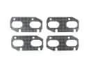 Toyota Matrix Exhaust Manifold Gasket
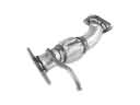 Toyota Matrix Exhaust Pipe
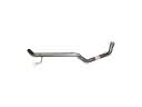 Toyota Matrix Tail Pipe
 Toyota Matrix Vapor Canister
 Toyota Matrix Vapor Pressure Sensor