×
ToyotaParts- Hello
- Login or Register
- Quick Links
- Live Chat
- Track Order
- Parts Availability
- RMA
- Help Center
- Contact Us
- Shop for
- Toyota Parts
- Scion Parts
My Garage
My Account
Cart
OEM Toyota Matrix Power Steering Pump
Power Steering Pump Unit- Select Vehicle by Model
- Select Vehicle by VIN
Select Vehicle by Model
orMake
Model
Year
Select Vehicle by VIN
For the most accurate results, select vehicle by your VIN (Vehicle Identification Number).
2 Power Steering Pumps found


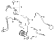
Toyota Matrix Power Steering Pump Part Number: 44310-02101
$348.89 MSRP: $511.30You Save: $162.41 (32%)Ships in 1-2 Business Days

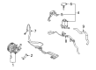
Toyota Matrix Power Steering Pump Part Number: 44310-01030
$299.98 MSRP: $428.30You Save: $128.32 (30%)Ships in 1-3 Business Days
Toyota Matrix Power Steering Pump
Choose genuine Power Steering Pump that pass strict quality control tests. You can trust the top quality and lasting durability. Shopping for OEM Power Steering Pump for your Toyota Matrix? Our website is your one-stop destination. We stock an extensive selection of genuine Toyota Matrix parts. The price is affordable so you can save more. It only takes minutes to browse and find the exact fit. Easily add to cart and check out fast. Our hassle-free return policy will keep you stress-free. We process orders quickly for swift delivery. Your parts will arrive faster, so you can get back on the road sooner.
Toyota Matrix Power Steering Pump Parts and Q&A
- Q: How to reassemble the Power Steering Pump on Toyota Matrix?A:The power steering vane pump reassembly process starts with installing a new vane pump housing oil seal which requires coating of its lip with power steering fluid followed by the correct usage of Special Service Tools: 09950-60010 09951-00280 for installation checks that seal orientation remains accurate. Start by applying power steering fluid on the inside bushing surface of the vane pump housing front and then insert the vane pump shaft slowly while protecting the oil seal lip from harm. Use a new O-ring that is power steering fluid coated to both the vane pump housing front and the side plate front and ensure their dent lines match before installation. Position the cam ring dent in line with the side plate front edge and put the cam ring in place with its inscribed mark facing outwards before installing the rotor which should also display its mark looking outward. You should cover 10 vane plates with power steering fluid before installing them outward facing with the round edge visible. After this install a new snap ring onto the pulley shaft sub-assembly using a snap ring expander to close it. Insert the vane pump housing rear's new O-ring that has been coated in power steering fluid with a straight pin alignment then bolt it using four bolts tightened to 22 Nm (220 kgf-cm, 16 ft-lbf). The preload check requires measurement of a smooth rotation without noise abnormalities through installation of a service bolt with dimensions 10 mm diameter and 1.25 mm pitch and 50 mm length. Review the rotating torque readings which should be less than or equal to 0.27 Nm (2.8 kgf-cm, 2.4 ft-lbf). Add the power steering oil pressure switch by applying power steering fluid to a new O-ring before fastening it to the vane pump assembly at 21 Nm torque (210 kgf-cm or 15 ft-lbf). You should drench the flow control valve compression spring and flow control valve with power steering fluid before mounting them and applying power steering fluid to a new O-ring on the pressure port union which needs to be fastened with 69 Nm torque pressure (700 kgf-cm, 51 ft-lbf). Various O-ring replacements follow a procedure which includes coating them with power steering fluid for the power steering suction port union followed by bolt installation at 12 Nm (120 kgf-cm, 9 ft-lbf). The vane pump bracket rear obtains final installation at 37 Nm (380 kgf-cm, 27 ft-lbf) torqued with a bolt.
- Q: How to overhaul the power steering pump on Toyota Matrix?A:The power steering pump overhaul starts with taking away the front wheel RH together with draining power steering fluid and removing the engine under cover RH. The first step requires removal of the fan and generator V belt and followed by disconnecting the oil reservoir to pump hose No.1 by removing its clip. Disembark the pressure feed tube assembly by employing Special Service Tool: 09023-38400 to remove the bolt from the pressure feed tube clamp. Separate the oil pressure switch connector after you remove the two bolts, nuts and vane pump assembly. Start by removing the bolt maintaining the vane pump bracket rear then take out the power steering pump heat insulator (4WD drive type). Set the vane pump assembly inside a vise with Special Service Tool: 09630-00014 (09631-00132). Then remove the power steering suction port union by unscrewing its bolt and O-ring. First detach the flow control valve after removing its compression spring and the pressure port union with its installed O-ring. After carefully extracting the oil pressure switch examine it for any damages as a new replacement is required if damaged. Detach the vane pump housing rear through removal of 4 bolts and extract the O-ring from the vane pump housing front. To remove the w/pulley shaft sub-assembly follow the procedure of snapping off the ring before taking out the vane pump rotor and its 10 plates. Pull out the vane pump cam ring together with the vane pump side plate front while properly extracting the O-rings. The vane pump housing oil seal extraction requires the Special Service Tool: 09631-10030 with a hammer to perform safely without damaging the pump housing. To check the oil clearance, use micrometer and caliper gauge tools and replace the vane pump assembly when the clearance reaches above 0.07 mm (0.0028 inch). Measurements of vane plates height and thickness and length need replacement when they fall below specified minimums. Assess the flow control valve for its operational smoothness and leakage then replace the assembly if required. The free spring length measurement of the flow control valve compression spring requires replacement when it falls below 36.9 mm (1.453 inch). The pressure port union should be checked for damage allowing for replacement if damage is present. Place a brand-new vane pump housing oil seal with the proper orientation before installing the w/pulley shaft sub-assembly while avoiding damage to the seal lip. Mount the vane pump side plate front with correct alignment while installing its corresponding O-rings. Place the vane pump cam ring first then add the rotor before setting the vane plates using a new snap ring. Front installation of the vane pump housing should feature a new O-ring positioned correctly before torqueing to 22 Nm (220 kgf-cm, 16 ft. lbs.). The preload measurement depends on free pump rotation without noise while using an approved service bolt to record the torque output between 0.27 Nm up to 2.8 kgf-cm and 2.4 ft. lbs. The power steering oil pressure switch requires a fresh O-ring before torquing to 21 Nm (210 kgf-cm, 15 ft. lbs.) while the flow control valve along with its compression spring and a new O-ring for the pressure port union must be installed next following torque to 69 Nm (700 kgf-cm, 51 ft. lbs.). Apply torque of 12 Nm (120 kgf-cm, 9 ft. lbs.) to install the power steering suction port union with a new O-ring. Afterwards, put on the power steering pump heat insulator (4WD drive type) followed by the vane pump bracket rear and torque them to 37 Nm (380 kgf-cm, 27 ft. lbs.). Secure the vane pump assembly by tightening the 2 bolts and nuts to 37 Nm while directing the oil pressure switch connector without any oil residue present. Use Special Service Tool: 09023-38400 to establish the pressure feed tube assembly before torquing to 41 Nm (420 kgf-cm, 30 ft. lbs.) and fasten the pressure feed tube clamp with the bolt requiring a torque of 7.8 Nm (80 kgf-cm, 69 ft. lbs.). Use the clip to connect oil reservoir pump hose No.1 while installing front wheel RH and generator fan V belt then torque both components to 103 Nm (1,050 kgf-cm, 76 ft. lbs.). Conclusion includes fluid addition of power steering followed by system bleeding and leak inspection before fitting the RH engine under cover.


Related Toyota Matrix Parts
 Toyota Matrix Steering Wheel
 Toyota Matrix Drag Link
 Toyota Matrix Power Steering Control Valve
 Toyota Matrix Power Steering Hose
 Toyota Matrix Power Steering Reservoir
 Toyota Matrix Rack And Pinion
 Toyota Matrix Rack and Pinion Boot
 Toyota Matrix Steering Column Cover
 Toyota Matrix Steering Gear Box
 Toyota Matrix Steering Shaft
 Toyota Matrix Tie Rod End
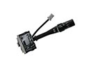 Toyota Matrix Windshield Wiper Switch