×
ToyotaParts- Hello
- Login or Register
- Quick Links
- Live Chat
- Track Order
- Parts Availability
- RMA
- Help Center
- Contact Us
- Shop for
- Toyota Parts
- Scion Parts
My Garage
My Account
Cart
OEM 2007 Toyota Matrix Power Steering Pump
Power Steering Pump Unit- Select Vehicle by Model
- Select Vehicle by VIN
Select Vehicle by Model
orMake
Model
Year
Select Vehicle by VIN
For the most accurate results, select vehicle by your VIN (Vehicle Identification Number).
1 Power Steering Pump found


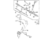
2007 Toyota Matrix Power Steering Pump
Part Number: 44310-02101$347.62 MSRP: $496.33You Save: $148.71 (30%)Ships in 1-2 Business DaysProduct Specifications- Other Name: Pump Assembly, Vane; Pump
- Part Name Code: 44320
- Item Weight: 10.60 Pounds
- Item Dimensions: 8.1 x 6.1 x 5.9 inches
- Condition: New
- Fitment Type: Direct Replacement
- SKU: 44310-02101
- Warranty: This genuine part is guaranteed by Toyota's factory warranty.
2007 Toyota Matrix Power Steering Pump
Looking for affordable OEM 2007 Toyota Matrix Power Steering Pump? Explore our comprehensive catalogue of genuine 2007 Toyota Matrix Power Steering Pump. All our parts are covered by the manufacturer's warranty. Plus, our straightforward return policy and speedy delivery service ensure an unparalleled shopping experience. We look forward to your visit!
2007 Toyota Matrix Power Steering Pump Parts Q&A
- Q: How to service and repair the power steering pump on 2007 Toyota Matrix?A: The procedure for servicing and repairing power steering pumps starts with removing the front wheel right side followed by draining power steering fluid and removing the right side engine under cover. Start the power steering pump service by removing the fan and generator V belt alongside disconnecting oil reservoir to pump hose No. 1 with its clip and separating the pressure feed tube assembly with Special Service Tool: 09023-38401 followed by unbolt and unclamping the pressure feed tube. The vane pump assembly removal starts with disconnecting the oil pressure switch connector before removing two bolts and nuts. Start vane pump bracket rear disassembly by removing the bolt followed by using Special Service Tool: 09630-00014 (09631-00132) to fix the vane pump assembly in a vise for disassembly. First remove the power steering suction port union bolt with its O-ring and subsequently disconnect the flow control valve with its compression spring through removal of the pressure port union and its O-ring. Handle the oil pressure switch with caution before removing the vane pump housing rear by taking away 4 bolts and the O-ring from the vane pump housing front. Detach the w/ pulley shaft sub-assembly through snap ring and vane plate removal and subsequent removal of the vane pump rotor. To proceed you should pull out the vane pump cam ring and the vane pump side plate front plus their O-rings. Employ Special Service Tool: 09631-10030 and strike the vane pump housing oil seal with a hammer to extract it while protecting the pump housing from damage. Use a micrometer and caliper gauge to check the oil clearance until it meets the standard and maximum clearance specifications. Use a micrometer to measure the height of the vane pump rotor and measure thickness of all vane pump plates before evaluating the rotor groove-vane plate clearance. Check if the flow control valve operates without problems and evaluates its leakage rate before measuring the flow control valve compression spring free length. The vane pump assembly requires new components if any component exceeds specification or shows damage. To reassemble the vane pump housing install a new oil seal prepared with power steering fluid by using Special Service Tools 09950-60010 (09951-00280), 09950-70010 (09951-07100) and a press tool according to proper orientation. The vane pump shaft insertion needs to be done slowly to safeguard the oil seal lip before side plate front and cam ring installation with the dent marks correctly positioned. Add the vane pump rotor to its position afterwards applying power steering fluid to the vane plates. After using a snap ring expander to add a fresh snap ring you should install the rear vane pump housing while utilizing a new O-ring. Perform this task by maintaining correct alignment and torquing it to 22 Nm (220 kgf/cm, 16 ft. lbs.). Check the pump preload through rotation tests and torque measurement that must be less than or equal to 0.27 Nm (2.8 kgf/cm, 2.4 ft. lbs). Grasp the power steering oil pressure switch after installing its new O-ring and set torque to 21 Nm (210 kgf/cm, 15 ft. lbs.), then proceed to fasten the flow control valve along with all its attaching components while maintaining correct torque torques for each interconnection. After installing two bolts and nuts that secure the vane pump assembly you should connect the oil pressure switch connector and use Special Service Tool: 09023-38401 during pressure feed tube assembly reassembly at correct torque values. The procedure includes reattachment of the oil reservoir to pump hose No.1 together with the reinstallation of the fan V belt and generator followed by front wheel RH, power steering fluid addition, system bleeder operation, leak inspection and the engine under cover RH installation.
Related 2007 Toyota Matrix Parts
 2007 Toyota Matrix Ignition Switch
 2007 Toyota Matrix Steering Wheel
 2007 Toyota Matrix Drag Link
 2007 Toyota Matrix Power Steering Hose
 2007 Toyota Matrix Power Steering Reservoir
 2007 Toyota Matrix Rack And Pinion
 2007 Toyota Matrix Rack and Pinion Boot
 2007 Toyota Matrix Steering Column
 2007 Toyota Matrix Steering Column Cover
 2007 Toyota Matrix Steering Gear Box
 2007 Toyota Matrix Steering Shaft
 2007 Toyota Matrix Tie Rod End