×
ToyotaParts- Hello
- Login or Register
- Quick Links
- Live Chat
- Track Order
- Parts Availability
- RMA
- Help Center
- Contact Us
- Shop for
- Toyota Parts
- Scion Parts
My Garage
My Account
Cart
OEM 2008 Toyota Matrix Rack And Pinion
Steering Rack And Pinion- Select Vehicle by Model
- Select Vehicle by VIN
Select Vehicle by Model
orMake
Model
Year
Select Vehicle by VIN
For the most accurate results, select vehicle by your VIN (Vehicle Identification Number).
1 Rack And Pinion found

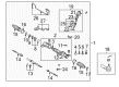
2008 Toyota Matrix Steering Gear
Part Number: 44250-01021$653.07 MSRP: $957.08You Save: $304.01 (32%)Ships in 1-3 Business DaysProduct Specifications- Other Name: Gear Assembly, Power Steering; Rack and Pinion Assembly; Steering Gearbox; Gear Assembly; Gear Assembly, Power Steering(For Rack & Pinion)
- Replaces: 44250-01020
- Part Name Code: 44250
- Item Weight: 14.40 Pounds
- Item Dimensions: 56.5 x 11.2 x 7.0 inches
- Condition: New
- Fitment Type: Direct Replacement
- SKU: 44250-01021
- Warranty: This genuine part is guaranteed by Toyota's factory warranty.
2008 Toyota Matrix Rack And Pinion
Looking for affordable OEM 2008 Toyota Matrix Rack And Pinion? Explore our comprehensive catalogue of genuine 2008 Toyota Matrix Rack And Pinion. All our parts are covered by the manufacturer's warranty. Plus, our straightforward return policy and speedy delivery service ensure an unparalleled shopping experience. We look forward to your visit!
2008 Toyota Matrix Rack And Pinion Parts Q&A
- Q: How to reassemble the power steering rack and pinion gear on 2008 Toyota Matrix?A: The power steering rack and pinion assembly requires the installation of power steering control valve lower bearing which should receive a molybdenum disulfide lithium base grease coating and implementation by means of special service tools 09950-60010 09951-00220 and a press. Install the power steering cylinder tube oil seal lip after coating it with power steering fluid by using special service tool: 09950-60010 09951-00240 and a press tool while maintaining the proper orientation. The installation of the power steering rack includes soaking its new power piston O-ring and oil seal in power steering fluid before expanding the oil seal carefully while using special service tool: 09631-16020. The installation of rack bush oil seals requires special service tools: 09950-60010 09951-00400 and a press for correct orientation positioning. Afterward install the new O-ring with power steering fluid. Special service tool: 09612-22011 combined with a hammer drives in the cylinder end stopper after which snap ring pliers allow installation of the new snap ring. The procedure for the rack and pinion assembly requires using special service tool: 09631-12071 with 53 kPa (400 mmHg, 15.75 in. Hg) vacuum for 30 seconds to test vacuum stability. Handle an upper bearing and new upper oil seal with power steering fluid before installing them using special service tool: 09950-60010 09951-00180 and 09950-60010 09951-00190. The technician should install four new control valve rings that need power steering fluid coating before placement into the control valve. Then he must put the control valve into the valve housing without damaging the rings. After applying power steering fluid to the needle bearing users must install the new gasket and fasten the valve housing to the rack housing by torqueing two bolts to 18 Nm (185 kgf-cm, 13 ft-lbf). Use the special service tools 09612-22011 09616-00011 to stop control valve shaft rotation before installing the self-locking nut to 25 Nm (250 kgf-cm, 18 ft-lbf). Apply threads of the rack housing cap with sealant (Part No. 08833-00080, three bond 1344, loctite 242 or equivalent) before installing with 59 Nm (600 kgf-cm, 43 ft-lbf). Complete installation by punching and hammering a stake. Cover the power steering rack and rack guide contact surfaces with molybdenum disulfide lithium base grease before installing the rack guide with compression spring and temporarily mounting the rack guide spring cap with sealant. Inspection of total preload requires using special service tool 09616-00011 09922-10010 to adjust it between 1.0 - 1.8 Nm (20 - 18 kgf-cm, 8.6 - 15.7 in-lbf) while holding the RH and LH rack ends temporarily in place. During this procedure, torque the rack guide spring cap to 25 Nm (250 kgf-cm, 18 ft-lbf) then back it off 12 degrees. The installation of the rack and pinion end sub-assembly requires using special service tool: 09922-10010 to tighten it to 62 Nm (630 kgf-cm, 46 ft-lbf) while maintaining a clear rack hole. Use special service tool: 09521-24010 to tighten rack boot No. 2 while keeping it at 2.0 mm (0.079 in.) clearance, then add the rack boot clip. Apply boot installation steps once again for rack boot No. 1. Seal the tie rod end sub-assemblies LH and RH onto the rack end by using the lock nut until the matchmark positions match. The right and left turn pressure tubes require new O-rings treated with power steering fluid before their installation to the rack and pinion assembly at 12 Nm (120 kgf-cm, 9 ft-lbf) torque using special service tool: 09023-38201.
Related 2008 Toyota Matrix Parts
 2008 Toyota Matrix Ignition Switch
 2008 Toyota Matrix Power Steering Pump
 2008 Toyota Matrix Steering Wheel
 2008 Toyota Matrix Drag Link
 2008 Toyota Matrix Power Steering Hose
 2008 Toyota Matrix Power Steering Reservoir
 2008 Toyota Matrix Rack and Pinion Boot
 2008 Toyota Matrix Steering Column
 2008 Toyota Matrix Steering Column Cover
 2008 Toyota Matrix Steering Gear Box
 2008 Toyota Matrix Steering Shaft
 2008 Toyota Matrix Tie Rod End