×
ToyotaParts- Hello
- Login or Register
- Quick Links
- Live Chat
- Track Order
- Parts Availability
- RMA
- Help Center
- Contact Us
- Shop for
- Toyota Parts
- Scion Parts
My Garage
My Account
Cart
OEM 2003 Toyota Matrix Rack And Pinion
Steering Rack And Pinion- Select Vehicle by Model
- Select Vehicle by VIN
Select Vehicle by Model
orMake
Model
Year
Select Vehicle by VIN
For the most accurate results, select vehicle by your VIN (Vehicle Identification Number).
3 Rack And Pinions found

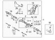
2003 Toyota Matrix Steering Gear
Part Number: 44250-01021$653.07 MSRP: $957.08You Save: $304.01 (32%)Ships in 1-3 Business DaysProduct Specifications- Other Name: Gear Assembly, Power Steering; Rack and Pinion Assembly; Steering Gearbox; Gear Assembly; Gear Assembly, Power Steering(For Rack & Pinion)
- Replaces: 44250-01020
- Part Name Code: 44250
- Item Weight: 14.40 Pounds
- Item Dimensions: 56.5 x 11.2 x 7.0 inches
- Condition: New
- Fitment Type: Direct Replacement
- SKU: 44250-01021
- Warranty: This genuine part is guaranteed by Toyota's factory warranty.
2003 Toyota Matrix Steering Gear
Part Number: 44250-01041$634.05 MSRP: $928.99You Save: $294.94 (32%)Ships in 1-3 Business DaysProduct Specifications- Other Name: Gear Assembly, Power Steering; Rack and Pinion Assembly; Steering Gearbox; Gear Assembly; Gear Assembly, Power Steering(For Rack & Pinion)
- Replaces: 44250-01040
- Part Name Code: 44250
- Item Weight: 17.10 Pounds
- Item Dimensions: 49.2 x 10.6 x 6.7 inches
- Condition: New
- Fitment Type: Direct Replacement
- SKU: 44250-01041
- Warranty: This genuine part is guaranteed by Toyota's factory warranty.

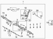 Product Specifications
- Other Name: Rack Sub-Assembly, Power; Steering Gearbox; Steering Rack; Rack Sub-Assembly, Power Steering
- Part Name Code: 44204
- Item Weight: 5.70 Pounds
- Item Dimensions: 32.4 x 3.1 x 2.8 inches
- Condition: New
- Fitment Type: Direct Replacement
- SKU: 44204-02060
- Warranty: This genuine part is guaranteed by Toyota's factory warranty.
2003 Toyota Matrix Rack And Pinion
Looking for affordable OEM 2003 Toyota Matrix Rack And Pinion? Explore our comprehensive catalogue of genuine 2003 Toyota Matrix Rack And Pinion. All our parts are covered by the manufacturer's warranty. Plus, our straightforward return policy and speedy delivery service ensure an unparalleled shopping experience. We look forward to your visit!
2003 Toyota Matrix Rack And Pinion Parts Q&A
- Q: What Are the Comprehensive Steps and Torque Specifications for Disassembling, Inspecting, Reassembling, and Installing the Rack and Pinion on 2003 Toyota Matrix?A: Coat power steering parts or grease when installing. Disassemble the battery, examine the wheel and disassemble the horn and steering wheel structures. Take off front wheels, covers, and disconnect parts with SST tools. Take off different assemblies, check and fit parts, torque and align properly. Add power steering fluid, bleed and leak check. Re-assemble and re-adjust.
Related 2003 Toyota Matrix Parts
 2003 Toyota Matrix Ignition Switch
 2003 Toyota Matrix Power Steering Pump
 2003 Toyota Matrix Steering Wheel
 2003 Toyota Matrix Power Steering Control Valve
 2003 Toyota Matrix Power Steering Hose
 2003 Toyota Matrix Power Steering Reservoir
 2003 Toyota Matrix Rack and Pinion Boot
 2003 Toyota Matrix Steering Column Cover
 2003 Toyota Matrix Steering Gear Box
 2003 Toyota Matrix Steering Shaft
 2003 Toyota Matrix Tie Rod End
 2003 Toyota Matrix Wiper Switch