×
ToyotaParts- Hello
- Login or Register
- Quick Links
- Live Chat
- Track Order
- Parts Availability
- RMA
- Help Center
- Contact Us
- Shop for
- Toyota Parts
- Scion Parts
My Garage
My Account
Cart
OEM 2006 Toyota Matrix Rack And Pinion
Steering Rack And Pinion- Select Vehicle by Model
- Select Vehicle by VIN
Select Vehicle by Model
orMake
Model
Year
Select Vehicle by VIN
For the most accurate results, select vehicle by your VIN (Vehicle Identification Number).
3 Rack And Pinions found

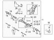
2006 Toyota Matrix Steering Gear
Part Number: 44250-01021$653.07 MSRP: $957.08You Save: $304.01 (32%)Ships in 1-3 Business DaysProduct Specifications- Other Name: Gear Assembly, Power Steering; Rack and Pinion Assembly; Steering Gearbox; Gear Assembly; Gear Assembly, Power Steering(For Rack & Pinion)
- Replaces: 44250-01020
- Part Name Code: 44250
- Item Weight: 14.40 Pounds
- Item Dimensions: 56.5 x 11.2 x 7.0 inches
- Condition: New
- Fitment Type: Direct Replacement
- SKU: 44250-01021
- Warranty: This genuine part is guaranteed by Toyota's factory warranty.
2006 Toyota Matrix Steering Gear
Part Number: 44250-01041$634.05 MSRP: $928.99You Save: $294.94 (32%)Ships in 1-3 Business DaysProduct Specifications- Other Name: Gear Assembly, Power Steering; Rack and Pinion Assembly; Steering Gearbox; Gear Assembly; Gear Assembly, Power Steering(For Rack & Pinion)
- Replaces: 44250-01040
- Part Name Code: 44250
- Item Weight: 17.10 Pounds
- Item Dimensions: 49.2 x 10.6 x 6.7 inches
- Condition: New
- Fitment Type: Direct Replacement
- SKU: 44250-01041
- Warranty: This genuine part is guaranteed by Toyota's factory warranty.

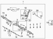 Product Specifications
- Other Name: Rack Sub-Assembly, Power; Steering Gearbox; Steering Rack; Rack Sub-Assembly, Power Steering
- Part Name Code: 44204
- Item Weight: 5.70 Pounds
- Item Dimensions: 32.4 x 3.1 x 2.8 inches
- Condition: New
- Fitment Type: Direct Replacement
- SKU: 44204-02060
- Warranty: This genuine part is guaranteed by Toyota's factory warranty.
2006 Toyota Matrix Rack And Pinion
Looking for affordable OEM 2006 Toyota Matrix Rack And Pinion? Explore our comprehensive catalogue of genuine 2006 Toyota Matrix Rack And Pinion. All our parts are covered by the manufacturer's warranty. Plus, our straightforward return policy and speedy delivery service ensure an unparalleled shopping experience. We look forward to your visit!
2006 Toyota Matrix Rack And Pinion Parts Q&A
- Q: What Are the Complete Procedures and Precautions for Disassembling, Inspecting, and Reassembling the Power Rack And Pinion Assembly on 2006 Toyota Matrix?A: Power steering fluid or molybdenum disulfide lithium base grease should be used for coating the marked parts when installation occurs. Disconnect the negative battery terminal while inspecting the center front wheel and remove the horn button assembly followed by the steering wheel assembly by using SST 09950-50013 (09951-05010, 09952-05010, 09953-05020, 09954-05021). Taking off the front wheels and engine under covers along with LH and RH items is the first step before removing the cotter pin, nut, and disconnecting the LH tie rod end sub-assembly using SST 09628-62011 from the steering knuckle. Repeat for the RH side. Start by removing the column hole cover silencer sheet before using SST 09023-38400 to disconnect both the pressure feed tube assembly and the return tube sub-assembly. To complete the disconnection separate the tube clamp by removing its single bolt. The bolt removal along with tube clamp disconnection applies to 4WD systems. The maintenance procedure requires removal of front stabilizer link assemblies LH and RH followed by disconnecting front suspension arm sub-assemblies lower No.1 LH and RH before removing hood sub-assembly and cylinder head cover No.2. The engine hangers receive two bolts for suspension while maintaining correct direction before engine chain hoist attachment. The crossmember sub-assembly requires removal after disconnecting both the frame and engine mounting insulator FR connections and separating the crossmember from the engine mounting insulator RR. A transmission jack supports the crossmember during removal when operators take away both the crossmember and rack and pinion assembly. The steering column hole cover sub-assembly No.1 should be removed while disconnecting the steering intermediate shaft with matchmarks before removing the rack and pinion assemblythrough its 4 bolts. Place SST 09612-00012 in a vise to secure the rack and pinion assemblywhile using SST 09023-38200 as tool to remove both steering left and right turn pressure tubes along with their associated O-rings. The technician must check torque specifications on both tie rod end sub-assemblies before removing them. The technician removes steering rack boots No.1 and No.2 afterward removing the steering rack end sub-assembly using SST 09922-10010. They need to mark the RH and LH rack ends during the removal process. Thoroughly examine the rack guide and power steering control valve along with their components by avoiding damage to the rings that fit into the control valve. First inspect the power steering rack for wear and run out and follow appropriate installation of new bearings as well as seals with correct lubrication and positioning. Begin assembly with the power steering rack bush sub-assembly, cylinder end stopper and power steering control valve along with its parts while orienting all seals for correct installation. Adjust total preload of the rack guide before adding the steering rack end sub-assembly with boots which requires adherence to torque specifications. After connecting the tie rod end components proceed with the installation of engine under covers and front wheels and examination of the center front wheel. The process ends in order with the installation of the column hole cover silencer sheet followed by power steering fluid addition and system bleeding and leak checking before reinstalling the cylinder head cover No.2 alongside the hood sub-assembly for necessary adjustment until the steering wheel and horn button assemblies can be installed and evaluated front wheel alignment and SRS warning light inspection.
Related 2006 Toyota Matrix Parts
 2006 Toyota Matrix Ignition Switch
 2006 Toyota Matrix Power Steering Pump
 2006 Toyota Matrix Steering Wheel
 2006 Toyota Matrix Drag Link
 2006 Toyota Matrix Power Steering Hose
 2006 Toyota Matrix Power Steering Reservoir
 2006 Toyota Matrix Rack and Pinion Boot
 2006 Toyota Matrix Steering Column
 2006 Toyota Matrix Steering Column Cover
 2006 Toyota Matrix Steering Gear Box
 2006 Toyota Matrix Steering Shaft
 2006 Toyota Matrix Tie Rod End