×
ToyotaParts- Hello
- Login or Register
- Quick Links
- Live Chat
- Track Order
- Parts Availability
- RMA
- Help Center
- Contact Us
- Shop for
- Toyota Parts
- Scion Parts
My Garage
My Account
Cart
OEM Toyota Corolla Rack And Pinion
Steering Gear- Select Vehicle by Model
- Select Vehicle by VIN
Select Vehicle by Model
orMake
Model
Year
Select Vehicle by VIN
For the most accurate results, select vehicle by your VIN (Vehicle Identification Number).
45 Rack And Pinions found


Toyota Corolla Steering Gear Part Number: 45510-02490
$568.96 MSRP: $833.82You Save: $264.86 (32%)Ships in 1-2 Business Days


Toyota Corolla Steering Gear Part Number: 45510-02171
$628.55 MSRP: $921.15You Save: $292.60 (32%)Ships in 1-3 Business Days
Toyota Corolla Steering Gear, Front Part Number: 45510-02360
$568.96 MSRP: $833.82You Save: $264.86 (32%)Ships in 1-2 Business DaysToyota Corolla Gear Assembly Part Number: 45510-12451
$626.62 MSRP: $918.32You Save: $291.70 (32%)Ships in 1-3 Business Days
Toyota Corolla Rack Part Number: 44204-12170
$341.16 MSRP: $499.97You Save: $158.81 (32%)Ships in 1-3 Business DaysToyota Corolla Steering Gear Part Number: 45510-12590
$568.96 MSRP: $833.82You Save: $264.86 (32%)Ships in 1-2 Business DaysToyota Corolla Steering Gear Part Number: 45510-02370
$568.96 MSRP: $833.82You Save: $264.86 (32%)Ships in 1-3 Business DaysToyota Corolla Steering Gear Part Number: 45510-12580
$590.64 MSRP: $865.59You Save: $274.95 (32%)Ships in 1-2 Business Days
Toyota Corolla Steering Gear Part Number: 44250-02070
$587.41 MSRP: $860.85You Save: $273.44 (32%)Ships in 1-3 Business DaysToyota Corolla Steering Gear Part Number: 44250-02151
$634.05 MSRP: $929.20You Save: $295.15 (32%)Ships in 1-3 Business DaysToyota Corolla Rack, Front Part Number: 44204-02010
$330.03 MSRP: $471.21You Save: $141.18 (30%)Ships in 1-3 Business Days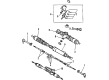
Toyota Corolla Steering Gear Part Number: 44250-12231-84
$332.88 MSRP: $467.79You Save: $134.91 (29%)Ships in 1-3 Business Days
Toyota Corolla Gear Assembly Part Number: 44250-12041
$657.97 MSRP: $974.21You Save: $316.24 (33%)Ships in 1-3 Business Days
Toyota Corolla Gear Assembly Part Number: 45510-12250
$422.79 MSRP: $619.60You Save: $196.81 (32%)Ships in 1-3 Business Days
Toyota Corolla Steering Gear Part Number: 45510-12270
$608.76 MSRP: $892.14You Save: $283.38 (32%)Ships in 1-3 Business DaysToyota Corolla Gear Assembly Part Number: 44250-12080
$638.09 MSRP: $935.13You Save: $297.04 (32%)Ships in 1-3 Business Days
Toyota Corolla Rack Part Number: 45521-20050
$32.66 MSRP: $45.45You Save: $12.79 (29%)Ships in 1-3 Business Days
Toyota Corolla Rack Part Number: 45521-12100
$90.07 MSRP: $126.44You Save: $36.37 (29%)Ships in 1-3 Business Days
Toyota Corolla Gear Assembly Part Number: 44250-12081-84
$327.51 MSRP: $396.77You Save: $69.26 (18%)Ships in 1-3 Business Days
Toyota Corolla Steering Gear Part Number: 44250-12160-84
| Page 1 of 3 |Next >
1-20 of 45 Results
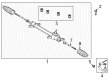
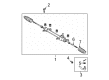
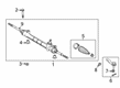
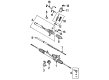
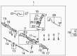
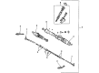
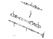
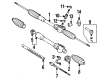
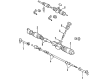
Toyota Corolla Rack And Pinion
Choose genuine Rack And Pinion that pass strict quality control tests. You can trust the top quality and lasting durability. Shopping for OEM Rack And Pinion for your Toyota Corolla? Our website is your one-stop destination. We stock an extensive selection of genuine Toyota Corolla parts. The price is affordable so you can save more. It only takes minutes to browse and find the exact fit. Easily add to cart and check out fast. Our hassle-free return policy will keep you stress-free. We process orders quickly for swift delivery. Your parts will arrive faster, so you can get back on the road sooner.
Toyota Corolla Rack And Pinion Parts and Q&A
- Q: What Are the Proper Steps, Required Tools, and Torque Specifications for Removing, Overhauling, and Reinstalling the Power Rack And Pinion Assembly on Toyota Corolla?A:The installation requires coating the parts marked by arrows with power steering fluid or molybdenum disulfide lithium base grease. First disconnect the negative terminal of the battery then check the center front wheel while removing the horn button assembly and Steering Wheel assembly by using SST 09950-50013 (09951-05010, 09952-05010, 09953-05020, 09954-05021). Disconnect the tie rod end sub-assembly LH by removing its cotter pin and nut then using SST 09628-62011 to separate it from the Steering Knuckle. Start by removing the front wheels and both engine under covers. Repeat for the RH side. Begin by taking off the column hole cover silencer sheet and proceed with disconnecting the steering intermediate shaft through SST 09023-38400 before moving onto the pressure feed tube assembly then return tube sub-assembly. First disconnect both front stabilizer link assemblies then separate the lower sub-assemblies of front suspension arm units from their left-hand and right-hand sides. You should first detach the hood sub-assembly, cylinder head cover No.2 while suspending the engine assembly by installing the two engine hangers (No.1 engine hanger: 12281-22021, No.2 engine hanger: 12281-15040, Bolt: 91512-B1016, Torque: 38 Nm). The front suspension crossmember sub-assembly requires removal by disconnecting it from the engine mounting insulator FR and the frame which can be supported by a transmission jack before removing the bolts. Start your procedure by detaching No.1 steering column hole cover sub-assembly and its components including steering intermediate shaft and rack and pinion power steering assembly using full bolt removal. Dismount the left and right turn pressure tubes with SST 09023-38200 before removing the O-rings when the rack and pinion power steering assembly sits in a vise that uses SST 09612-00012. Check the torque specifications of LH and RH tie rod end sub-assemblies after their removal. SST 09922-10010 helps users uninstall the steering rack end sub-assembly after they remove both steering rack boots No.1 and No.2 by clearly marking the RH and LH rack ends. Begin by removing the rack guide and power steering control valve and their neighboring components to check for damage and wear on the power steering rack. The new bearings receive proper positioning and receive required lubrication during integration. Sealants and torque requirements should be used during reassembly of the power steering control valve and rack assembly. Reinstall the steering rack end sub-assemblies to the steering rack hole before placing steering rack boots. The technician will combine the tie rod ends with engine under covers and front wheels before inspecting the center front wheel and adjusting steering wheel alignment. After power steering fluid addition and system bleeding you need to check for any signs of leakage then replace the cylinder head cover No.2 along with the hood sub-assembly while making necessary adjustments and achieving correct wheel alignment and SRS warning light operation.
- Q: How to remove the rack and pinion power steering gear on Toyota Corolla?A:The first process to extract the rack and pinion power steering rack and pinion includes aligning front wheels straight ahead before removing front wheels. Your first step should be removing both engine under covers from the left and right sides then disconnecting the Exhaust Pipe assembly in front. The practitioner must disconnect the left tie rod end sub-assembly through removal of the cotter pin and nut before using Special Service Tool: 09628-62011 to detach it from the Steering Knuckle. Complete the right tie rod end sub-assembly process in exactly the same manner. First remove the two clips that secure the column hole cover silencer sheet before attaching a seat belt to prevent wheel rotation to mark the intermediate shaft assembly No. 2 and the intermediate shaft. First loosen bolt A before removing bolt B which allows separation of the intermediate shaft assembly No. 2. For assembly sub-assembly No. 1 disconnect the pressure feed tube assembly by removing its bolt and tube clamp from the power steering rack and pinion while using Special Service Tool: 09023-12701. The first step entails removal of the front stabilizer link assemblies from each side after disconnecting the front suspension arm sub-assemblies lower No. 1 from both left and right sides. The hood sub-assembly and cylinder head cover No. 2 can be removed before the engine assembly suspension through installation of two engine hangers (Parts No.: No. 1 engine hanger 12281-22021, No. 2 engine hanger 12281-15040, Bolt 91512-B1016). Engine hangers No. 1 (12281-22021) and No. 2 engine hanger (12281-15040) with bolt 91512-B1016 must be installed before use of the chain hoist for engine support. The hoist needs to avoid attaching to any other section of the engine. To begin the process remove the four bolts securing the front suspension crossmember sub-assembly before splitting the center member from the rest of the parts and disconnecting the engine mounting insulator RR from the crossmember. The front suspension crossmember sub-assembly including rack and pinion assembly will come out after supporting the crossmember with a transmission jack and removing its four bolts. The final step includes placing matchmarks on the steering intermediate shaft before removing its bolt and shaft then the rack and pinion power steering rack and pinion assembly can be removed by taking out the four crossmember bolts while maintaining the nut from rotating during the bolt torque process.


Related Toyota Corolla Parts
 Toyota Corolla Steering Wheel
 Toyota Corolla Power Steering Pump
 Toyota Corolla Power Steering Hose
 Toyota Corolla Power Steering Reservoir
 Toyota Corolla Steering Column
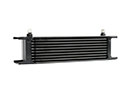 Toyota Corolla Power Steering Cooler
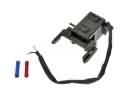 Toyota Corolla Shift Interlock Solenoid
 Toyota Corolla Steering Column Cover
 Toyota Corolla Steering Gear Box
 Toyota Corolla Steering Shaft
 Toyota Corolla Tie Rod End
 Toyota Corolla Windshield Wiper Switch