×
ToyotaParts- Hello
- Login or Register
- Quick Links
- Live Chat
- Track Order
- Parts Availability
- RMA
- Help Center
- Contact Us
- Shop for
- Toyota Parts
- Scion Parts
My Garage
My Account
Cart
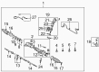
OEM 2006 Toyota Corolla Rack And Pinion
Steering Rack And Pinion- Select Vehicle by Model
- Select Vehicle by VIN
Select Vehicle by Model
orMake
Model
Year
Select Vehicle by VIN
For the most accurate results, select vehicle by your VIN (Vehicle Identification Number).
3 Rack And Pinions found

2006 Toyota Corolla Steering Gear
Part Number: 44250-02151$634.05 MSRP: $929.20You Save: $295.15 (32%)Ships in 1-3 Business DaysProduct Specifications- Other Name: Gear Assembly, Power Steering; Rack and Pinion Assembly; Steering Gearbox; Gear Assembly; Gear Assembly, Power Steering(For Rack & Pinion)
- Manufacturer Note: (L)
- Replaces: 44250-02150
- Part Name Code: 44250
- Item Weight: 14.60 Pounds
- Item Dimensions: 50.7 x 10.9 x 6.6 inches
- Condition: New
- Fitment Type: Direct Replacement
- SKU: 44250-02151
- Warranty: This genuine part is guaranteed by Toyota's factory warranty.
2006 Toyota Corolla Steering Gear
Part Number: 44250-02070$587.41 MSRP: $860.85You Save: $273.44 (32%)Ships in 1-3 Business DaysProduct Specifications- Other Name: Gear Assembly, Power Steering; Rack and Pinion Assembly; Steering Gearbox; Rack & Pinion; Gear Assembly; Gear Assembly, Power Steering(For Rack & Pinion)
- Part Name Code: 44250
- Item Weight: 14.60 Pounds
- Item Dimensions: 50.2 x 10.8 x 6.6 inches
- Condition: New
- Fitment Type: Direct Replacement
- SKU: 44250-02070
- Warranty: This genuine part is guaranteed by Toyota's factory warranty.
 Product Specifications
- Other Name: Rack Sub-Assembly, Power; Steering Gearbox; Steering Rack; Rack Sub-Assembly, Power Steering
- Part Name Code: 44204
- Item Weight: 5.70 Pounds
- Item Dimensions: 32.4 x 3.1 x 2.8 inches
- Condition: New
- Fitment Type: Direct Replacement
- SKU: 44204-02060
- Warranty: This genuine part is guaranteed by Toyota's factory warranty.
2006 Toyota Corolla Rack And Pinion
Looking for affordable OEM 2006 Toyota Corolla Rack And Pinion? Explore our comprehensive catalogue of genuine 2006 Toyota Corolla Rack And Pinion. All our parts are covered by the manufacturer's warranty. Plus, our straightforward return policy and speedy delivery service ensure an unparalleled shopping experience. We look forward to your visit!
2006 Toyota Corolla Rack And Pinion Parts Q&A
- Q: How to Overhaul a Rack and Pinion Power Steering Assembly on 2006 Toyota Corolla?A: First install the cylinder end stopper with Special Service Tool: 09612-22011 and a hammer while snap ring pliers are necessary for placing a new snap ring at the rack housing. An air tightness test must be performed using Special Service Tool: 09631-12071 (09633-00010) to check the rack housing while you apply a vacuum of 53 kPa (398 mmHg, 15.65 inHg) for 30 seconds to determine the integrity of the oil seals. Feed power steering fluid into a new power steering control valve upper bearing combined with oil seal before using Special Service Tool: 09950-60010 (09951-00180, 09951-00320, 09952-06010), 09950-70010 (09951-07100) and a press to install both parts in their right direction. You should install the power steering control valve upper bearing through the same sequence of procedures. Special Service Tool: 09631-20081 should be used to guide the tapered end for installing four power steering fluid-coated control valve spacers onto the control valve assembly. Beginning with power steering fluid lubrication of the control valve spacers' oil seal lip, proceed to mount the control valve into its housing slot by maintaining protective distance from spacers and oil seal lip surfaces. Install the new power steering control valve lower oil seal lip by coating it with power steering fluid before use of Special Service Tool: 09612-22011 and a press for correct installation direction. New molybdenum disulfide lithium based grease requires application on the power steering valve center then on the lower bearings. After installing a new valve housing gasket secure the valve housing to the rack housing through 2 bolts set to 18 Nm torque. Wedge tool 09616-00011 should be used to stop valve rotation during new rack housing cap nut installation steps that require 25 Nm (250 kgf-cm, 18 ft. lbs.) torque and 2 or 3 threads of sealant (Part No. 08833-00080, Three Bond 1344, Loctite 242 or equivalent) before rack housing cap assembly. This step is followed by staking cap and housing with punch and hammer. Workplace grease should be applied to the contact area of power steering components followed by rack guide and spring setup before applying sealant to rack guide spring threads. The rack guide should then be installed for a brief fitment. The total preload inspection can be performed by applying 25 Nm torque to rack guide spring cap while installing RH and LH rack ends. Next, apply 120 degrees counter-torque to the cap before using Special Service Tool: 09616-00011 to rotate the control valve shaft. Install the rack guide spring cap with a generous amount of sealant on its threads and secure it only until the preloaded service rating is between 1.0 and 1.8 Nm (10 to 18 kgf-cm or 8.9 to 15.9 inch lbs.). The hexagon wrench (19 mm) should secure the cap during nut torquing with Special Service Tool: 09922-10010 that reaches 42 Nm (428 kgf-cm, 31 ft. lbs.) but always verify the total preload in the correct direction. The installation of the rack and pinion power steering rack end sub-assembly requires a secure rack hold while using Special Service Tool: 09922-10010 to torque the 2 rack ends to 60 Nm (614 kgf-cm, 44 ft. lbs.) while checking for grease inside the rack hole. Attach steering rack boot No.2 after applying silicon grease to its small aperture and fasten it to the rack housing and end and then perform the same process for boot No.1. Attachment of new rack boot No.2 clamps to the LH side requires Special Service Tool: 09521-24010 followed by attachment to the RH side. Use metal clips to secure the rack boots while monitoring their movement with the control valve through the use of Special Service Tool: 09616-00011. The tie rod end sub-assemblies should be connected to each rack end through correct matchmark alignment followed by lock nut torque application. The steering right turn pressure tube requires installation with 2 new O-rings coated in power steering fluid using Special Service Tool: 09023-38201 and following torquing up to 12 Nm (120 kgf-cm, 9 ft. lbs.). This process needs repetition for the left turn pressure tube installation. Set the rack and pinion power steering rack assembly into position using 4 bolts and nuts while torquing them to 58 Nm (591 kgf-cm, 43 ft. lbs.) without using any torque screwdriver technique. The installation of the steering intermediate shaft requires proper alignment of matchmarks before securing it with a bolt torqued to 35 Nm (360 kgf-cm, 26 ft. lbs.). Fasten the steering column hole cover sub-assemblage No.1 and the front suspension crossmember sub-assemblage with Special Service Tool: 09670-00010 during installation before torquing the components to exact torque specifications. Insert the engine mounting insulators RR and FR into cross and center members then torque to indicated specifications. The front suspension lower arms and stabilizer links (LH and RH) should be connected to their corresponding parts then torqued to stated values. The pressure feed tube assembly requires use of Special Service Tool: 09023-12701 followed by torquing to 23 Nm (229 kgf-cm, 17 ft. lbs.). The tube clamp receives a final torque of 7.8 Nm (80 kgf-cm, 69 ft. lbs.) at the power steering rack assembly. Connect the steering intermediate shaft using bolts marked with matchmarks before torquing bolt B to 35 Nm while tightening bolt A. Then install the tie rod end sub-assemblies (LH and RH) with proper nuts torqued to 49 Nm and new cotter pins must be installed. The installation process includes placing the 1ZZ-FE and 2ZZ-GE engine type exhaust pipe assembly then adding the engine under covers from the LH and RH sides along with securing the front wheels with a torque of 103 Nm (1,050 kgf-cm, 76 ft. lbs.). To finalize the installation the mechanic must position front wheels directly ahead before implementing the column hole cover silencer sheet and adding power steering fluid for system bleeding followed by leak inspections of the cylinder head cover No.2 and hood sub-assembly and front wheel alignment correction.
Related 2006 Toyota Corolla Parts
 2006 Toyota Corolla Steering Wheel
 2006 Toyota Corolla Power Steering Pump
 2006 Toyota Corolla Power Steering Hose
 2006 Toyota Corolla Power Steering Reservoir
 2006 Toyota Corolla Steering Column
 2006 Toyota Corolla Wiper Switch
 2006 Toyota Corolla Drag Link
 2006 Toyota Corolla Power Steering Control Valve
 2006 Toyota Corolla Rack and Pinion Boot
 2006 Toyota Corolla Steering Column Cover
 2006 Toyota Corolla Steering Gear Box
 2006 Toyota Corolla Steering Shaft