- Hello
- Login or Register
- Quick Links
- Live Chat
- Track Order
- Parts Availability
- RMA
- Help Center
- Contact Us
- Shop for
- Toyota Parts
- Scion Parts

Popular OEM Toyota Corolla Parts
- Body & Hardware Parts View More >
- Electrical Parts View More >
- Engine Parts View More >
- Air & Fuel Delivery Parts View More >
- Belts & Cooling Parts View More >
- Steering Parts View More >
- Suspension Parts View More >
- Emission Control & Exhaust Parts View More >
- A/C & Heating Parts View More >
- Charging & Starting Parts View More >
- Brakes Parts View More >
- Transmission Parts View More >


Why Buy Genuine Toyota Corolla Parts From ToyotaPartsNow.com
ToyotaPartsNow.com highlights the reliability of OEM Toyota Corolla parts right at your fingertips. Our skilled staff assists customers in selecting the right Toyota Corolla parts and provides expert help with any unique part requests. At ToyotaPartsNow.com, we make all Toyota Corolla parts available to you quickly and efficiently through our fast order and reliable ship process. Our service is designed to make finding the correct Toyota Corolla parts fast and easy whether you are an amateur or a professional. We offer access to a broad inventory that includes a wide range of Toyota years and variants. Affordable prices, quick processing and professional service are also our specialty to ensure your car remains in top condition with OEM Toyota Corolla parts, including Headlights & Lighting. You can feel confident shopping with us because all Toyota Corolla parts, such as Driveline & Axles you purchase from our store are of genuine quality and built to last.
The Toyota Corolla became popular in the automotive industry during its first launch in 1966 and reached 50 million unit sales across twelve generations. After its launch with a simple 1100 cc piston engine Toyota Corolla received the performance and efficiency improvements of the 1ZZ-FE engine during the late 1990s. The engine choices for the Corolla included gasoline alongside diesel and many of its variants utilized front-wheel drive but the AE85 and AE86 models delivered rear-wheel drive performance. The Corolla's transmission systems have evolved significantly, from the simple mechanical setups in earlier models to the advanced automatic and manual transmissions available today, with the introduction of CVT systems in later generations for improved fuel efficiency. The E90 generation received multiple upgrades when it launched in 1987 because its new aerodynamic appearance combined with all-wheel drive availability in certain models which expanded its situational capabilities. Since its inception Toyota set reliability as its primary goal alongside user-friendly maintenance thus genuine Toyota auto parts maintain peak performance and long-lasting operation. The components used for Toyota vehicles undergo stringent quality checks before final approval because they meet the manufacturer's precise specifications which enhances the Corolla's known reputation for long-lasting performance. Toyota's engineering greatness along with their commitment to developing dependable cars makes the Toyota Corolla stand as a symbol of their production excellence while adapting to present-day market needs.
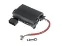
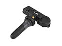
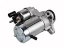
Toyota Corolla drivers often face three common problems tied to the engine, transmission, and emissions parts. First, the Check Engine light may come on as a result of an EVAP leak. A broken charcoal canister or a loose gas cap lets fumes escape and triggers the code. The replacement of the canister or tightening of the cap clears the light and maintains clean air. Second, old models of Toyota Corolla with approximately 125,000 to 150,000 miles can jerk or fail to shift. Rough shifts are usually due to a Toyota Corolla throttle position sensor that is out of range or a worn shift solenoid. A new sensor or solenoid provides smooth gear changes without the trouble of taking apart the complete transmission. Third, a silent starter circuit can leave a Toyota Corolla resting at home as the odometer reads 100,000 to 125,000 miles. Brushes that are worn out in the starter or contacts that have been burnt in the solenoid can block current flow. The fix that will restore dependable starts and prevent towing bills is a rebuilt starter or a low-cost contact kit. Resolve these issues early to save on fuel, wallet and keep the Toyota Corolla safe on the road. Regular fluid inspection, the replacement of parts, even some basic tests keep the Toyota Corolla functioning well for many more years.
Toyota Corolla Parts and Q&A
- Q: How to service and repair the steering wheel on Toyota Corolla?A:When doing the steering wheel it is advisable to begin by removing the steering wheel pad and steering wheel followed by removing the upper and lower column covers. Next, detach the spiral cable. To reassemble, the spiral cable must be installed then the column covers then the steering wheel then the steering wheel pad.
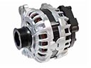
- Q: How to remove the alternator on Toyota Corolla?A:In order to take out the alternator, disconnect the negative battery terminal, take out the engine under cover, and the V-ribbed belt. Next, remove the terminal cap, disconnect the wire harness and remove the bolts that hold the generator assembly and wire harness clamp bracket.
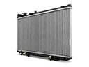
- Q: How to remove and reinstall a radiator on Toyota Corolla?A:The radiator can be removed by draining out the engine coolant and taking off the under covers. Dissolve the electric cooling fan connections, radiator hoses, and oil cooler hoses. Take out supports and bolts, and then radiator assembly. Take apart and examine parts and make sure they are reassembled correctly. Leak check, reinstall radiator and repair hose and fans.


