×
ToyotaParts- Hello
- Login or Register
- Quick Links
- Live Chat
- Track Order
- Parts Availability
- RMA
- Help Center
- Contact Us
- Shop for
- Toyota Parts
- Scion Parts
My Garage
My Account
Cart
OEM Toyota Corolla Wheel Bearing
Hub Bearing- Select Vehicle by Model
- Select Vehicle by VIN
Select Vehicle by Model
orMake
Model
Year
Select Vehicle by VIN
For the most accurate results, select vehicle by your VIN (Vehicle Identification Number).
35 Wheel Bearings found


Toyota Corolla Hub Assembly Part Number: 43550-47020
$309.65 MSRP: $442.10You Save: $132.45 (30%)Ships in 1-3 Business Days


Toyota Corolla Wheel Bearing Part Number: 90080-36136
$59.83 MSRP: $83.98You Save: $24.15 (29%)Ships in 1-3 Business Days

Toyota Corolla Hub & Bearing, Rear Part Number: 42450-02170
$413.13 MSRP: $605.44You Save: $192.31 (32%)Ships in 1-3 Business Days

Toyota Corolla Hub Assembly, Front Part Number: 43550-02090
$226.00 MSRP: $322.67You Save: $96.67 (30%)Ships in 1-3 Business Days

Toyota Corolla Hub & Bearing, Rear Part Number: 42450-01010
$528.44 MSRP: $774.44You Save: $246.00 (32%)Ships in 1-3 Business Days

Toyota Corolla Front Hub Part Number: 43502-12090
$144.04 MSRP: $203.91You Save: $59.87 (30%)Ships in 1-3 Business Days


Toyota Corolla Wheel Hub, Front Part Number: 43502-02080
$125.48 MSRP: $177.63You Save: $52.15 (30%)


Toyota Corolla Bearing (For Front Drive Shaft) Part Number: 90080-36133
$32.13 MSRP: $44.73You Save: $12.60 (29%)Ships in 1-2 Business Days

Toyota Corolla Axle Support Bearing Part Number: 90363-36004
$37.87 MSRP: $52.71You Save: $14.84 (29%)Ships in 1-3 Business Days

Toyota Corolla Wheel Bearing Part Number: 90368-29068
$33.21 MSRP: $46.22You Save: $13.01 (29%)Ships in 1-3 Business Days
Toyota Corolla Rear Hub & Bearing Part Number: 42450-02290
$268.75 MSRP: $383.72You Save: $114.97 (30%)Ships in 1-2 Business Days
Toyota Corolla Hub & Bearing, Rear Part Number: 42450-12170
$405.41 MSRP: $594.13You Save: $188.72 (32%)Ships in 1 Business Day

Toyota Corolla Hub & Bearing Assembly, Rear Axle, Passenger Side Part Number: 42450-76021
$268.99 MSRP: $384.05You Save: $115.06 (30%)Ships in 1-2 Business Days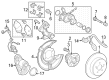
Toyota Corolla Rear Hub & Bearing Part Number: 42450-12231
$356.72 MSRP: $522.78You Save: $166.06 (32%)Ships in 1-2 Business Days
Toyota Corolla Hub Assembly Part Number: 42410-12090
$361.83 MSRP: $530.26You Save: $168.43 (32%)Ships in 1-3 Business Days
Toyota Corolla Hub Assembly Part Number: 42410-01020
$404.84 MSRP: $593.30You Save: $188.46 (32%)Ships in 1-3 Business Days

Toyota Corolla Wheel Bearing, Rear Part Number: 90369-28006
$163.90 MSRP: $232.02You Save: $68.12 (30%)

Toyota Corolla Front Hub Part Number: 43502-12070
$168.72 MSRP: $238.84You Save: $70.12 (30%)

Toyota Corolla Wheel Bearing, Front Part Number: 90369-38003-77


Toyota Corolla Hub, Front Part Number: 43502-12110
| Page 1 of 2 |Next >
1-20 of 35 Results
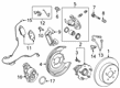
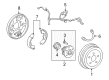
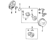
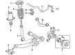
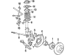
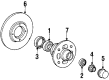
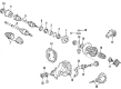
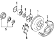
Toyota Corolla Wheel Bearing
Choose genuine Wheel Bearing that pass strict quality control tests. You can trust the top quality and lasting durability. Shopping for OEM Wheel Bearing for your Toyota Corolla? Our website is your one-stop destination. We stock an extensive selection of genuine Toyota Corolla parts. The price is affordable so you can save more. It only takes minutes to browse and find the exact fit. Easily add to cart and check out fast. Our hassle-free return policy will keep you stress-free. We process orders quickly for swift delivery. Your parts will arrive faster, so you can get back on the road sooner.
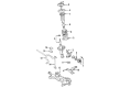
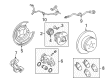
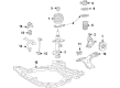
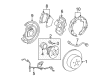
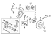
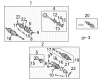
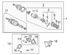
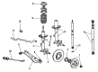
The Wheel Bearing is arguably one of the main parts that defines the reliability of any of the Toyota Corolla brand of cars. The wheel bearing is exceptionally known to be very durable and plays the role of allowing the wheels to rotate with ease while at the same time reducing the friction of the wheel and tires assembly. This is important in ensuring the safety and interaction of the Toyota Corolla as bad wheel bearings bring about noise, vibration, and at one point brings out detachments of the wheels. This Wheel Bearing is fit for numerous models of the Corolla both front-wheel drive and all-wheel drive, exhibiting its versatility in the Corolla line. Rather curiously, it is worth mentioning that most Corolla models have an integral hub and bearing assembly that very often includes an ABS sensor, and this assembly is replaced as a single unit, which makes it much easier to service. In this standpoint, it must be noted that the wheel bearing concerns periodic checks to check for rough surface or any loosening that may affect safety. The Wheel Bearing is unique to the automotive market by its sturdiness of the product and high-quality material utilised in the constructions contributing to the durableness of the car. Thus, focusing on the wheel bearings of the car, Toyota Corolla owners can prolong the driving properties of their vehicle and prevent undesired situations on the road.
Toyota Corolla Wheel Bearing Parts and Q&A
- Q: How to service and repair the wheel bearing on Toyota Corolla?A:The beginning of wheel bearing service requires wheel removal in the front position. The wheel bearing backlash and axle hub deviation can be checked through disc and Brake Caliper removal and proper support of the brake caliper before measurements. A dial indicator should measure the backlash near the center of the axle hub to ensure the measurement stays below 0.05 mm (0.0020 inch); if the value exceeds this threshold you need to change the bearing. The measurement of axle hub deviation at the surface beyond the bolt area needs to be below 0.07 mm (0.0028 inch) to pass inspection. If this standard is not met a new axle hub replacement is needed. After restoring the disc together with the brake caliper and its two bolts apply torque to 88 Nm (900 kgf.cm, 65 ft. lbs.). The driver should begin to apply parking brake force then unscrew the drive shaft lock nut after first grabbing the cotter pin and lock cap. Repeat the sequence of removing 2 bolts followed by the brake caliper and disc and then support the brake caliper appropriately. The ABS speed sensor needs removal in ABS-equipped vehicles by removing its bolt. The Shock Absorber flexible hose can be detached by undoing its securing bolt. You can begin tie rod end disconnection from the Steering Knuckle by first removing the cotter pin and nut while using Special Service Tool: 09628-62011. The process requires removal of the bolt connected to the lower Ball Joint followed by removal of the 2 nuts before taking out the steering knuckle with its axle hub. Perform this step while carefully avoiding any damage to the boot and ABS speed sensor rotor. Install the steering knuckle with axle hub while being cautious to protect the boot and ABS speed sensor rotor, apply engine oil on the 2 nuts' threads before installing the 2 shock absorber lower bolts and nuts with a torque of 274 Nm (2,800 kgf.cm, 203 ft. lbs.). Fasten the lower suspension arm to the lower ball joint by torquing it to 142 Nm (1,450 kgf.cm, 105 ft. lbs.). Once you attach the tie rod end to the steering knuckle you should begin with installing the nut along with the new cotter pin then increase the nut tightening up to 60 degrees if the holes are misaligned before torqueing to 49 Nm (500 kgf.cm, 36 ft. lbs.). You should replace the flexible hose by torquing it to 29 Nm (300 kgf.cm) and apply 22 ft. lbs. Finally screw in the ABS speed sensor using 8.0 Nm (82 kgf.cm, 71 inch lbs.) torque. To install the drive shaft lock nut, first reinstall the disc followed by the brake caliper and 2 bolts which require torquing to 88 Nm (900 kgf.cm, 65 ft. lbs.). You must then install the nut with tightened torque of 225 Nm (2,300 kgf.cm, 166 ft. lbs.) under brake application before installing lock cap and a new cotter pin and cautiously tightening the nut up to 60 degrees if needed. The installation of the front wheel starts with checking bearing backlash and axle hub deviation before final torquing to 103 Nm (1,050 kgf.cm, 76 ft. lbs.). Follow this procedure by depressing the brake pedal several times while checking the front wheel alignment together with an ABS speed sensor signal verification.

Related Toyota Corolla Parts
 Toyota Corolla Brake Pads
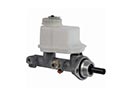 Toyota Corolla Brake Master Cylinder
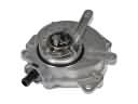 Toyota Corolla Vacuum Pump
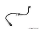 Toyota Corolla Brake Booster Vacuum Hose
 Toyota Corolla Brake Booster Vacuum Pump
 Toyota Corolla Brake Drum
 Toyota Corolla Brake Fluid Pump
 Toyota Corolla Hydraulic Hose
 Toyota Corolla Master Cylinder Repair Kit
 Toyota Corolla Spindle Nut
 Toyota Corolla Wheel Cylinder Repair Kit
 Toyota Corolla Yaw Sensor