×
ToyotaParts- Hello
- Login or Register
- Quick Links
- Live Chat
- Track Order
- Parts Availability
- RMA
- Help Center
- Contact Us
- Shop for
- Toyota Parts
- Scion Parts
My Garage
My Account
Cart
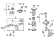
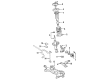
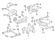
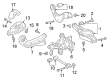
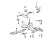
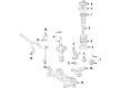
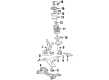
OEM Toyota Corolla Control Arm
Suspension Arm- Select Vehicle by Model
- Select Vehicle by VIN
Select Vehicle by Model
orMake
Model
Year
Select Vehicle by VIN
For the most accurate results, select vehicle by your VIN (Vehicle Identification Number).
30 Control Arms found


Toyota Corolla Lower Control Arm, Driver Side Part Number: 48069-02310
$159.20 MSRP: $225.37You Save: $66.17 (30%)Ships in 1-3 Business Days

Toyota Corolla Control Arm, Lower Driver Side Part Number: 48069-02190
$173.54 MSRP: $245.66You Save: $72.12 (30%)Ships in 1 Business Day
Toyota Corolla Control Arm, Passenger Side Part Number: 48068-02190
$173.54 MSRP: $245.66You Save: $72.12 (30%)Ships in 1-3 Business Days


Toyota Corolla Control Arm, Passenger Side Part Number: 48068-02021
$192.10 MSRP: $274.27You Save: $82.17 (30%)Ships in 1-3 Business Days

Toyota Corolla Upper Control Arm, Rear Driver Side Part Number: 48790-47010
$132.53 MSRP: $187.61You Save: $55.08 (30%)Ships in 1-3 Business Days


Toyota Corolla Upper Control Arm, Rear Driver Side Part Number: 48790-06010
$132.53 MSRP: $187.61You Save: $55.08 (30%)Ships in 1-3 Business Days
Toyota Corolla Lower Control Arm, Driver Side Part Number: 48069-13010
$167.90 MSRP: $237.68You Save: $69.78 (30%)Ships in 1-2 Business Days

Toyota Corolla Lower Control Arm, Passenger Side Part Number: 48068-13010
$167.90 MSRP: $237.68You Save: $69.78 (30%)Ships in 1-2 Business Days

Toyota Corolla Control Arm, Lower Driver Side Part Number: 48069-02021
$192.10 MSRP: $274.27You Save: $82.17 (30%)Ships in 1-3 Business DaysToyota Corolla Lower Control Arm, Passenger Side Part Number: 48068-02310
$159.20 MSRP: $225.37You Save: $66.17 (30%)Ships in 1-3 Business Days
Toyota Corolla Lower Control Arm, Front Driver Side Part Number: 48069-02301
$159.20 MSRP: $225.37You Save: $66.17 (30%)Ships in 1-3 Business DaysToyota Corolla Lower Control Arm, Front Passenger Side Part Number: 48068-02301
$159.20 MSRP: $225.37You Save: $66.17 (30%)Ships in 1-3 Business Days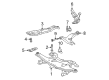
Toyota Corolla Lower Control Arm, Passenger Side Part Number: 48068-20390
$180.21 MSRP: $257.30You Save: $77.09 (30%)Ships in 1-3 Business DaysToyota Corolla Lower Control Arm, Driver Side Part Number: 48069-20390
$192.10 MSRP: $274.27You Save: $82.17 (30%)Ships in 1-3 Business Days
Toyota Corolla Lower Control Arm, Driver Side Part Number: 48069-12171
$192.10 MSRP: $274.27You Save: $82.17 (30%)Ships in 1-2 Business DaysToyota Corolla Lower Control Arm, Passenger Side Part Number: 48068-12171
$207.36 MSRP: $296.06You Save: $88.70 (30%)Ships in 1-3 Business Days
Toyota Corolla Control Arm, Lower Driver Side Part Number: 48069-12110
$168.44 MSRP: $238.44You Save: $70.00 (30%)Ships in 1-3 Business Days

Toyota Corolla Lower Control Arm, Passenger Side Part Number: 48068-12130
$153.00 MSRP: $216.58You Save: $63.58 (30%)Ships in 1-3 Business Days

Toyota Corolla Lower Control Arm, Driver Side Part Number: 48069-12130
| Page 1 of 2 |Next >
1-20 of 30 Results
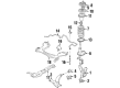
Toyota Corolla Control Arm
Choose genuine Control Arm that pass strict quality control tests. You can trust the top quality and lasting durability. Shopping for OEM Control Arm for your Toyota Corolla? Our website is your one-stop destination. We stock an extensive selection of genuine Toyota Corolla parts. The price is affordable so you can save more. It only takes minutes to browse and find the exact fit. Easily add to cart and check out fast. Our hassle-free return policy will keep you stress-free. We process orders quickly for swift delivery. Your parts will arrive faster, so you can get back on the road sooner.
Toyota Corolla Control Arm Parts and Q&A
- Q: How to remove the front lower Control Arm on Toyota Corolla?A:The first step to remove the front lower suspension arm requires wheel removal. The first step requires disconnection of the front stabilizer link assembly LH using LH (A/T) position and the second step follows with front stabilizer link assembly RH disconnection through identical procedures as the LH side. The lower front suspension arm sub-assembly No. 1 LH can be separated by removing its bolt and 2 nuts until it releases from the lower Ball Joint assembly front LH. You should repeat this exact procedure to detach the lower No. 1 RH front suspension arm sub-assembly. To perform the separation of the rack & pinion power steering gear assembly proceed with bolt removal of 4 units while using a wrench to free the bolt because the nut cannot be turned. Subsequently suspend the assembly. The engineer should suspend both the engine assembly as well as other components. To extract the front suspension crossmember sub-assembly use a transmission jack after unbolting 3 nuts and 3 bolts to discharge the transverse engine mounting insulator from the engine mounting member sub-assembly center and remove 4 bolts from the assembly before pulling down the jack to remove the sub-assembly. The procedure to separate the lower front suspension arm sub-assembly includes deinstalling two bolts along with a nut that connect it to the front suspension crossmember sub-assembly.
- Q: How to install the front lower Control Arm on Toyota Corolla?A:First tighten two bolts and a nut at the front suspension arm sub-assembly lower No. 1 LH before moving ahead. Next, lift the front suspension crossmember sub-assembly with a transmission jack and insert Special Service Tool: 09670-00010 into the base hole of the RH side crossmember and the RH side of the vehicle, then temporarily tighten the bolt in the order A and B. Repeat this process for the LH side of the crossmember, ensuring to tighten the bolts A and B to the specified torque of 157 Nm (1,601 kgf-cm, 116 ft-lbf) for Bolt A and 113 Nm (1,152 kgf-cm, 83 ft-lbf) for Bolt B. Connect the transverse engine mounting insulator and engine mounting member sub-assembly center to the front suspension crossmember sub-assembly, securing it with 3 bolts and 3 nuts at a torque of 52 Nm (530 kgf-cm, 38 ft-lbf). Secure the rack & pinion power steering gear at its four bolts by tightening them to 58 Nm (591 kgf-cm, 43 ft-lbf). Use low torque of 908 kgf-cm (89 Nm) to fix the lower No. 1 LH front suspension arm sub-assembly to the parking brake lower ball joint front LH using 2 nuts and a bolt. Rephrase the installation steps for the lower No. 1 front suspension arm sub-assembly on the right-hand side. Put the front stabilizer link assembly into place at the LH side then duplicate the steps at the RH side. Install the front wheel and lower the car for proper suspension adjustment. Tighten wheel bolts to 103 Nm (1,050 kgf-cm, 76 ft-lbf) and bounce the vehicle to settle the suspension. After suspending the vehicle properly you should tighten all 2 bolts and nut on the front suspension arm number 1 lower left support to produce 137 Nm (1,397 kgf-cm, 101 ft-lbf) torque while ensuring bolt tightening since nut rotation is prohibited. You should also inspect the front wheel alignment and perform needed adjustments.


Related Toyota Corolla Parts
 Toyota Corolla Sway Bar Link
 Toyota Corolla Axle Beam Mount
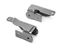 Toyota Corolla Control Arm Bracket
 Toyota Corolla Crossmember Bushing
 Toyota Corolla Lateral Link
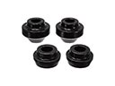 Toyota Corolla Radius Arm Bushing
 Toyota Corolla Rear Crossmember
 Toyota Corolla Strut Housing
 Toyota Corolla Sway Bar Bracket
 Toyota Corolla Sway Bar Bushing
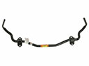 Toyota Corolla Sway Bars
 Toyota Corolla Trailing Arm Bushing
Browse Toyota Corolla Control Arm by Years
2025
2024
2023
2022
2021
2020
2019
2018
2017
2016
2015
2014
2013
2012
2011
2010
2009
2008
2007
2006
2005
2004
2003
2002
2001
2000
1999
1998
1997
1996
1995
1994
1993
1992
1991
1990
1989
1988
1987
1986
1985
1984