×
ToyotaParts- Hello
- Login or Register
- Quick Links
- Live Chat
- Track Order
- Parts Availability
- RMA
- Help Center
- Contact Us
- Shop for
- Toyota Parts
- Scion Parts
My Garage
My Account
Cart
OEM 2007 Toyota Corolla Control Arm
Suspension Arm- Select Vehicle by Model
- Select Vehicle by VIN
Select Vehicle by Model
orMake
Model
Year
Select Vehicle by VIN
For the most accurate results, select vehicle by your VIN (Vehicle Identification Number).
4 Control Arms found


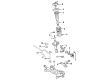
2007 Toyota Corolla Control Arm, Lower Driver Side
Part Number: 48069-02021$186.50 MSRP: $266.29You Save: $79.79 (30%)Ships in 1-3 Business DaysProduct Specifications- Other Name: Arm Sub-Assembly, Suspension; Suspension Control Arm, Front Left; Track Control Arm; Lower Control Arm; Arm Sub-Assembly, Front Suspension, Lower Driver Side; Suspension Control Arm
- Position: Lower Driver Side
- Replaces: 48069-02020
- Part Name Code: 48069
- Item Weight: 1.40 Pounds
- Item Dimensions: 21.6 x 16.3 x 5.7 inches
- Condition: New
- Fitment Type: Direct Replacement
- SKU: 48069-02021
- Warranty: This genuine part is guaranteed by Toyota's factory warranty.

2007 Toyota Corolla Control Arm, Passenger Side
Part Number: 48068-02021$186.50 MSRP: $266.29You Save: $79.79 (30%)Ships in 1-3 Business DaysProduct Specifications- Other Name: Arm Sub-Assembly, Suspension; Suspension Control Arm, Front Right; Track Control Arm; Lower Control Arm; Arm Sub-Assembly, Front Suspension, Lower Passenger Side; Suspension Control Arm
- Position: Passenger Side
- Replaces: 48068-02020
- Part Name Code: 48068
- Item Weight: 12.00 Pounds
- Item Dimensions: 20.4 x 20.1 x 9.4 inches
- Condition: New
- Fitment Type: Direct Replacement
- SKU: 48068-02021
- Warranty: This genuine part is guaranteed by Toyota's factory warranty.
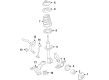
2007 Toyota Corolla Lower Control Arm, Driver Side
Part Number: 48069-20390$186.50 MSRP: $266.29You Save: $79.79 (30%)Ships in 1-3 Business DaysProduct Specifications- Other Name: Arm Sub-Assembly, Suspension; Suspension Control Arm; Control Arm
- Position: Driver Side
- Item Weight: 0.80 Pounds
- Item Dimensions: 2.5 x 1.7 x 1.6 inches
- Condition: New
- SKU: 48069-20390
- Warranty: This genuine part is guaranteed by Toyota's factory warranty.
2007 Toyota Corolla Lower Control Arm, Passenger Side
Part Number: 48068-20390$180.21 MSRP: $257.30You Save: $77.09 (30%)Ships in 1-3 Business DaysProduct Specifications- Other Name: Arm Sub-Assembly, Suspension; Suspension Control Arm; Control Arm
- Position: Passenger Side
- Item Weight: 0.80 Pounds
- Item Dimensions: 2.4 x 1.6 x 1.6 inches
- Condition: New
- SKU: 48068-20390
- Warranty: This genuine part is guaranteed by Toyota's factory warranty.
2007 Toyota Corolla Control Arm
Looking for affordable OEM 2007 Toyota Corolla Control Arm? Explore our comprehensive catalogue of genuine 2007 Toyota Corolla Control Arm. All our parts are covered by the manufacturer's warranty. Plus, our straightforward return policy and speedy delivery service ensure an unparalleled shopping experience. We look forward to your visit!
2007 Toyota Corolla Control Arm Parts Q&A
- Q: How to service and repair the front lower Control Arm on 2007 Toyota Corolla?A: Begin repairs or services of the front lower suspension arm by removing the front wheel before breaking the front stabilizer link assembly from both left-hand (LH) and right-hand (RH) sides. Perform procedures for both sides identically. Move on to the front suspension arm sub-assembly lower No. 1 LH by unbolt and unscrew the two nuts from the lower ball joint assembly front LH before performing the same operation for the right side. Use four bolts to divide the rack & pinion power steering gear assembly but only loosen one bolt since rotating the nut is impossible before suspending the assembly. The procedure entails suspending the engine assembly before isolating the front suspension crossmember sub-assembly by removing three bolts and three nuts to detach the transverse engine mounting insulator and engine mounting member sub-assembly center and finally removing four additional bolts from the transmission jack to drop the crossmember. Unfasten two suspension arm lower sub-assembly screws and one nut to remove the No. 1 LH component. Installation process begins by temporarily tightening the front suspension arm sub-assembly lower No. 1 LH then with the aid of a transmission jack the front suspension crossmember sub-assembly can be lifted before inserting Special Service Tool: 09670-00010 into both sides base holes to properly sequence bolt tightening. Both Bolt A and Bolt B undergo installation torque of 157 Nm (1,601 kgf-cm, 116 ft. lbs.) and 113 Nm (1,152 kgf-cm, 83 ft. lbs.) respectively. Afterward, install three bolts and three nuts with 52 Nm (530 kgf-cm, 38 ft. lbs.) torque to complete the reconnection of transverse engine mounting insulator and engine mounting member sub-assembly center. You must first install the rack & pinion power steering gear assembly with its four bolts tightened to 58 Nm (591 kgf-cm, 43 ft. lbs.) after which you must install the front suspension arm sub-assembly lower No. 1 LH with two nuts and a bolt at 89 Nm (908 kgf-cm, 66 ft. lbs.). The second step involves installing both front stabilizer link assemblies after completing the procedures for the RH side. Tighten the vehicle suspension with the front wheels on and the vehicle lowered while bouncing it several times. To complete installation tighten both bolts and the nut of the front suspension arm sub-assembly lower No. 1 LH all the way to 137 Nm (1,397 kgf-cm, 101 ft. lbs.). Ensure to tighten the bolt when the nut cannot be rotated because it is the last step before inspecting and making a front wheel alignment.
Related 2007 Toyota Corolla Parts
 2007 Toyota Corolla Sway Bar Link
 2007 Toyota Corolla Ball Joint
 2007 Toyota Corolla Coil Springs
 2007 Toyota Corolla Bump Stop
 2007 Toyota Corolla Coil Spring Insulator
 2007 Toyota Corolla Crossmember Bushing
 2007 Toyota Corolla Shock And Strut Mount
 2007 Toyota Corolla Shock and Strut Boot
 2007 Toyota Corolla Sway Bar Bracket
 2007 Toyota Corolla Sway Bar Bushing
 2007 Toyota Corolla Sway Bar Kit
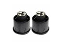 2007 Toyota Corolla Trailing Arm Bushing