×
ToyotaParts- Hello
- Login or Register
- Quick Links
- Live Chat
- Track Order
- Parts Availability
- RMA
- Help Center
- Contact Us
- Shop for
- Toyota Parts
- Scion Parts
My Garage
My Account
Cart
OEM 2007 Toyota Corolla Sway Bar Kit
Stabilizer Sway Bar Set- Select Vehicle by Model
- Select Vehicle by VIN
Select Vehicle by Model
orMake
Model
Year
Select Vehicle by VIN
For the most accurate results, select vehicle by your VIN (Vehicle Identification Number).
3 Sway Bar Kits found


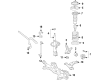
2007 Toyota Corolla Stabilizer Bar, Front
Part Number: 48811-AB011$122.54 MSRP: $173.47You Save: $50.93 (30%)Ships in 1-3 Business DaysProduct Specifications- Other Name: Bar, Stabilizer, Front; Suspension Stabilizer Bar, Front; Suspension Stabilizer Bar Kit; Stabilizer Bar Kit; Sway Bar
- Position: Front
- Replaces: 48811-AB010
- Part Name Code: 48811
- Item Weight: 13.60 Pounds
- Item Dimensions: 6.4 x 11.1 x 41.8 inches
- Condition: New
- Fitment Type: Direct Replacement
- SKU: 48811-AB011
- Warranty: This genuine part is guaranteed by Toyota's factory warranty.
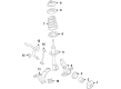
2007 Toyota Corolla Stabilizer Bar, Front
Part Number: 48811-12A60$119.96 MSRP: $169.82You Save: $49.86 (30%)Ships in 1-3 Business DaysProduct Specifications- Other Name: Bar, Stabilizer, Front; Suspension Stabilizer Bar, Front; Sway Bar
- Position: Front
- Replaces: 48811-12A00, 48811-12A70
- Part Name Code: 48811
- Item Weight: 5.40 Pounds
- Condition: New
- Fitment Type: Direct Replacement
- SKU: 48811-12A60
- Warranty: This genuine part is guaranteed by Toyota's factory warranty.

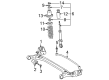
2007 Toyota Corolla Stabilizer Bar, Rear
Part Number: 48812-AB011$102.73 MSRP: $144.20You Save: $41.47 (29%)Ships in 1-3 Business DaysProduct Specifications- Other Name: Bar, Stabilizer, Rear; Suspension Stabilizer Bar, Rear; Sway Bar
- Position: Rear
- Replaces: 48812-AB010
- Part Name Code: 48812
- Item Weight: 4.90 Pounds
- Item Dimensions: 42.8 x 9.3 x 3.5 inches
- Condition: New
- Fitment Type: Direct Replacement
- SKU: 48812-AB011
- Warranty: This genuine part is guaranteed by Toyota's factory warranty.
2007 Toyota Corolla Sway Bar Kit
Looking for affordable OEM 2007 Toyota Corolla Sway Bar Kit? Explore our comprehensive catalogue of genuine 2007 Toyota Corolla Sway Bar Kit. All our parts are covered by the manufacturer's warranty. Plus, our straightforward return policy and speedy delivery service ensure an unparalleled shopping experience. We look forward to your visit!
2007 Toyota Corolla Sway Bar Kit Parts Q&A
- Q: How to service the rear Sway Bar Kit on 2007 Toyota Corolla?A: Service on the rear sway bar kit requires removing the sway bar kit rear by detaching its 2 bolts and nuts. Secure the sway bar kit rear by placing its marked left rear section first and tighten the bolts and nuts to 195 Nm (142 ft. lbs., 1988 kgf-cm).
Related 2007 Toyota Corolla Parts
 2007 Toyota Corolla Sway Bar Link
 2007 Toyota Corolla Ball Joint
 2007 Toyota Corolla Coil Springs
 2007 Toyota Corolla Control Arm Bushing
 2007 Toyota Corolla Steering Knuckle
 2007 Toyota Corolla Alignment Bolt
 2007 Toyota Corolla Axle Shaft
 2007 Toyota Corolla Control Arm Bolt
 2007 Toyota Corolla Front Cross-Member
 2007 Toyota Corolla Shock And Strut Mount
 2007 Toyota Corolla Shock and Strut Boot
 2007 Toyota Corolla Strut Housing