×
ToyotaParts- Hello
- Login or Register
- Quick Links
- Live Chat
- Track Order
- Parts Availability
- RMA
- Help Center
- Contact Us
- Shop for
- Toyota Parts
- Scion Parts
My Garage
My Account
Cart
OEM 2002 Toyota Corolla Rack And Pinion
Steering Rack And Pinion- Select Vehicle by Model
- Select Vehicle by VIN
Select Vehicle by Model
orMake
Model
Year
Select Vehicle by VIN
For the most accurate results, select vehicle by your VIN (Vehicle Identification Number).
2 Rack And Pinions found

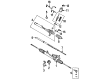
2002 Toyota Corolla Rack, Front
Part Number: 44204-02010$330.03 MSRP: $471.21You Save: $141.18 (30%)Ships in 1-3 Business DaysProduct Specifications- Other Name: Rack Sub-Assembly, Power; Rack And Pinion Rack Gear, Front; Steering Gearbox; Steering Rack; Rack Sub-Assembly, Power Steering
- Position: Front
- Part Name Code: 44204
- Item Weight: 5.80 Pounds
- Item Dimensions: 32.7 x 3.1 x 2.8 inches
- Condition: New
- Fitment Type: Direct Replacement
- SKU: 44204-02010
- Warranty: This genuine part is guaranteed by Toyota's factory warranty.

 Product Specifications
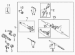
- Other Name: Gear Assembly, Power Steering; Rack and Pinion Assembly; Steering Gearbox; Gear Assembly; Gear Assembly, Power Steering(For Rack & Pinion)
- Part Name Code: 44250
- Item Weight: 16.50 Pounds
- Item Dimensions: 51.2 x 10.6 x 6.7 inches
- Condition: New
- Fitment Type: Direct Replacement
- SKU: 44250-02020
- Warranty: This genuine part is guaranteed by Toyota's factory warranty.
2002 Toyota Corolla Rack And Pinion
Looking for affordable OEM 2002 Toyota Corolla Rack And Pinion? Explore our comprehensive catalogue of genuine 2002 Toyota Corolla Rack And Pinion. All our parts are covered by the manufacturer's warranty. Plus, our straightforward return policy and speedy delivery service ensure an unparalleled shopping experience. We look forward to your visit!
2002 Toyota Corolla Rack And Pinion Parts Q&A
- Q: How to disassemble the Rack And Pinion on 2002 Toyota Corolla?A: Secure the rack and pinion assembly inside the vise using 09612-00012 special service tool before detaching the 2 turn pressure tubes by using special service tool: 09023-38200 to remove the 4 O-rings. First indicate the tie rod end and rack end positions before starting to loosen the lock nut which allows the tie rod end with its lock nut to be removed on both sides. The clamp can be unfastened using pliers to extract RH and LH clips, rack boots, and clamps while taking care to protect the boot and marking the RH and LH rack boots. The washer unstake can only happen with a chisel and hammer while keeping the rack and pinion out of impact zone. Remove the rack end along with the claw washer through tool special service tool: 09922-10010. The rack guide spring cap lock nut needs to be unlocked with same tool followed by removing the rack guide spring cap with a 19 mm hexagon wrench then pulling off the rack guide spring along with the conical spring washer then the rack guide subassembly. Remove the rack housing cap by applying special service tool: 09616-00011 to stop the control valve shaft from rotating and free the self-locking nut. Place matchmarks on the control valve housing and rack housing before removing 2 bolts. Then take out the control valve housing with attached control valve assembly while also taking off the gasket. Before removing the control valve assembly with its oil seal users should apply vinyl tape around the serrated section of the shaft followed by plastic hammer tapping of the assembly to protect the oil seal lip integrity. You should use special service tool: 09631-10021 to rotate the cylinder end stopper clockwise until the wire shaft becomes visible before turning it counterclockwise to access the wire. Special service tool: 09612-24014 (09612-10061) allows the rack and pinion to be pressed out together with the bushing before the O-ring is extracted from the bushing. Press out the oil seal by using special service tool: 09950-60010 (09951-00260), 09950-70010 (09951-07360) while avoiding damage to the rack housing. A dial indicator will help you check rack and pinion runout while measuring teeth wear up to 0.30 mm (0.0118 inch) and inspect the back surface for wear and damage. The installation process requires special service tool: 09950-60010 (09951-00260), 09950-70010 (09951-07100) for pressing in a new oil seal while coating its lip with power steering fluid before inserting it correctly. Install the new bearing with molybdenum disulfide lithium base grease before using special service tool: 09950-60010 (09951-00190, 09951-00360, 09952-06010), 09950-70010 (09951-07100) for insertion. Use special service tool: 09950-70010 (09951-07100) to press out the bearings for replacement on relevant occasions. New bearings need to be coated with molybdenum disulfide lithium base grease before insertion with the tool. The technician can replace the oil seal from the bushing through the usage of special service tool: 09612-24014 (09613-22011) while ensuring the bushing remains undamaged. Subsequently they should prepare a new oil seal by coating its lip with power steering fluid prior to pressing it in using special service tool: 09950-60010 (09951-00230, 09951-00370, 09952-06010), 09950-70010 (09951-07100). To replace the Teflon ring you should first remove it with a screwdriver then expand a new ring before coating it with power steering fluid followed by cautious installation. When installing the 4 Teflon rings into the control valve assembly you should first remove existing rings then expand fresh rings before coating them with power steering fluid and finally placing them in position without harming the grooves. Reassemble while applying power steering fluid or molybdenum disulfide lithium base grease to designated parts then place the oil seal using special service tools 09950-60010 (containing 09951-00240, 09951-00400 and 09952-06010) together with 09950-70010 (including 09951-07360) correctly oriented. Position the rack and pinion inside the housing after applying power steering fluid to it while using special service tool: 09631-16020. Place the bushing into position adopting the correct orientation while preserving power steering fluid on its O-ring to protect from damaging the oil seal lip. Fit the end stopper of the cylinder while placing the wire installation hole in line. Then use special service tool: 09631-10021 to turn it clockwise 450 plus or minus 50 degrees. Utilize special service tool: 09631-12071 while conducting an air tightness test by applying 53 kPa (400 mmHg, 15.75 inch Hg) vacuum pressure for about 30 seconds to check vacuum stability. Put together the control valve assembly while protecting the oil seal lip and applying power steering fluid on the Teflon rings before housing the assembly within the control valve housing. Apply correct orientation when pressing in the oil seal using special service tool: 09612-22011. Install the control valve housing with the control valve assembly by first applying a new gasket on the rack housing and then ensuring matchmark alignment before tightening the 2 bolts to 18 Nm (185 kgf-cm, 13 ft. lbs.). Use special service tool: 09616-00011 to install the self-locking nut after stopping the control valve shaft from rotation then torque it to 25 Nm (250 kgf-cm, 18 ft. lbs.). The rack housing cap installation requires sealant (Part No. 08833-00080, THREE BOND 1344, LOCTITE 242 or equivalent) before torquing to 59 Nm (600 kgf-cm, 43 ft. lbs.). Also use a punch and hammer to stake the two parts. The rack guide subassembly should be installed with a conical spring washer and rack guide spring followed by the rack guide spring cap where sealant will be applied to the threads. To adjust overall preload position, workers should install the RH and LH rack ends followed by tightening the rack guide spring cap to 25 Nm (250 kgf-cm, 18 ft. lbs.) while leaving the cap at a 12° angle and operating special service tool: 09616-00011 to manipulate the control valve shaft. Proceed by loosening the rack guide spring cap while releasing the spring force and tightly secure the cap to achieve 0.8 - 1.4 Nm (8 - 14 kgf-cm, 6.9 - 12.2 inch lbs.) preload. Install the rack guide spring cap lock nut with sealant after temporary installation and torque it to 43 Nm (439 kgf-cm, 32 ft. lbs.) using special service tool: 09922-10010 while rechecking total preload. Set the RH and LH rack ends into the rack and pinion grooves before torquing them to 62 Nm with special service tool: 09521-24010 while staking the washer and installing the RH and LH rack boots with clamps and clips to finish the assembly.
Related 2002 Toyota Corolla Parts
 2002 Toyota Corolla Steering Wheel
 2002 Toyota Corolla Power Steering Pump
 2002 Toyota Corolla Power Steering Hose
 2002 Toyota Corolla Power Steering Reservoir
 2002 Toyota Corolla Steering Column
 2002 Toyota Corolla Wiper Switch
 2002 Toyota Corolla Drag Link
 2002 Toyota Corolla Power Steering Control Valve
 2002 Toyota Corolla Rack and Pinion Boot
 2002 Toyota Corolla Steering Column Cover
 2002 Toyota Corolla Steering Gear Box
 2002 Toyota Corolla Steering Shaft