×
ToyotaParts- Hello
- Login or Register
- Quick Links
- Live Chat
- Track Order
- Parts Availability
- RMA
- Help Center
- Contact Us
- Shop for
- Toyota Parts
- Scion Parts
My Garage
My Account
Cart
OEM Toyota Tundra Rack And Pinion
Steering Gear- Select Vehicle by Model
- Select Vehicle by VIN
Select Vehicle by Model
orMake
Model
Year
Select Vehicle by VIN
For the most accurate results, select vehicle by your VIN (Vehicle Identification Number).
10 Rack And Pinions found


Toyota Tundra Gear Assembly Part Number: 44250-0C160
$556.03 MSRP: $814.86You Save: $258.83 (32%)Ships in 1-3 Business Days
Toyota Tundra Rack, Front Part Number: 44204-0C011
$597.91 MSRP: $876.24You Save: $278.33 (32%)Ships in 1-3 Business DaysToyota Tundra Gear Assembly Part Number: 44250-0C170
$653.07 MSRP: $957.08You Save: $304.01 (32%)Ships in 1-3 Business Days
Toyota Tundra Gear Assembly, Electric Part Number: 44250-0C210
$953.84 MSRP: $1397.87You Save: $444.03 (32%)Ships in 1-2 Business DaysToyota Tundra Gear Assembly, Electric Part Number: 44250-0C200
$953.84 MSRP: $1397.87You Save: $444.03 (32%)Ships in 1-2 Business Days


Toyota Tundra Steering Gear Part Number: 44250-0C010
$690.86 MSRP: $1012.47You Save: $321.61 (32%)
Toyota Tundra Rack, Front Part Number: 44204-0C010
Toyota Tundra Steering Gear Part Number: 44250-0C030
$653.07 MSRP: $957.08You Save: $304.01 (32%)Toyota Tundra Steering Gear Part Number: 44250-0C041
$722.76 MSRP: $1059.21You Save: $336.45 (32%)
Toyota Tundra Gear Assembly Part Number: 44250-0C131
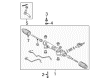
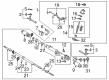
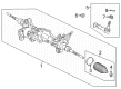
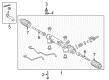
Toyota Tundra Rack And Pinion
Choose genuine Rack And Pinion that pass strict quality control tests. You can trust the top quality and lasting durability. Shopping for OEM Rack And Pinion for your Toyota Tundra? Our website is your one-stop destination. We stock an extensive selection of genuine Toyota Tundra parts. The price is affordable so you can save more. It only takes minutes to browse and find the exact fit. Easily add to cart and check out fast. Our hassle-free return policy will keep you stress-free. We process orders quickly for swift delivery. Your parts will arrive faster, so you can get back on the road sooner.
The Rack And Pinion in Toyota Tundra vehicles is used in the steering mechanism of the vehicle whereby, it translates the rotational movement of the steering wheel into lateral movement offront wheels. This mechanism utilizes the rack n pinion system in which the pinion which is the smaller gear is on a shaft and interlocks with the bigger gear which is the rack enclosed in a metal tube to allow for precise turning of the wheel. In the past years design, Tundra models mainly apply the passenger car standard power-assisted rack & pinion steering system to improve the ease and responsive driving. The control of these systems commonly involves hydraulic backing and this is where a liquid under pressure is directed in an axis of the rack through a piston. Manual racks have been used in past but currently most Tundra use hydraulic to get better performance. Some common problems which may be an indication that the Rack And Pinion requires general overhaul or even replacement include; leakage, gear wear down, and damaged seals.
Toyota Tundra Rack And Pinion Parts and Q&A
- Q: How to remove the power Rack And Pinion on Toyota Tundra?A:The first step for removing the power steering rack and pinion consists of disconnecting the negative battery cable and waiting at least 90 seconds after switch-off before reconnection; some systems need initialization after the cable is reconnected. Maintenance begins by aligning the front wheels forward then removing both wheels before removing the No. 1 engine under cover. To remove the No. 2 intermediate shaft assembly first, users need to disconnect tie rod end sub-assemblies starting with the left-hand side and then the right-hand side through step-by-step procedures. Demount the pressure feed tube assembly through disconnecting the pressure feed tube at both return and power steering rack and pinion locations using a union nut wrench and removing the two clamp bolts. The last step involves removing the power steering rack and pinion assembly after disconnecting all two bolts and two nuts but avoiding nut spin on its stopper. Loosen the bolt instead to protect the fixed nut in position.
- Q: How to properly install and adjust components in a Rack and Pinion steering assembly on Toyota Tundra?A:A vise should never be gripped excessively tight when in use. Fill the marked parts with either power steering fluid or molybdenum disulfide lithium base grease. Install the new oil seal through SST 09950-60010 (09951-00330, 09951-00490, 09952-06010) and SST 09950-70010 (09951-07360) by coating its lip with power steering fluid before carefully inserting it into the correct direction. Mount the rack and pinion with SST 09631-20051 before applying power steering fluid on the rack and inserting it into the rack housing without harming the oil seal lip and removing SST 09631-20051. Put new O-ring in power steering fluid before installing it to the bushing and protect the rack and pinion end by wrapping vinyl tape around it while installing the bushing in its proper direction. Align the rack housing slot with the wire installation hole of the cylinder end stopper then add a fresh wire before using SST 09631-16010 to adjust the stopper clock-wise between 400° and 500°. The air tightness test needs you to install SST 09631-12071 to the rack housing and maintain 53 kPa (400 mmHg, 15.75 in.Hg) vacuum pressure for thirty seconds. Assess oil seal performance if vacuum changes. The control valve assembly installation process requires step one to wrap vinyl tape onto the valve shaft serrations to hinder oil seal lip damage and step two to apply power steering fluid to Teflon rings before valve housing assembly insertion while paying attention to prevent damaging Teflon rings and the oil seal. Install a new oil seal lip into the correct direction by pressing it in using SST 09612-22011 while it remains coated with power steering fluid. Install the new gasket onto the rack housing then perfectly position the control valve assembly matchmark on the valve housing versus the rack housing before securing the 2 bolts to 18 Nm (185 kgf-cm, 13 ft. lbs.). SST 09616-00011 to eliminate control valve shaft motion and secure a new nut with proper torque at 30 Nm (300 kgf-cm, 22 ft. lbs.). Using tools SST 09816-30010 and SST 09616-00011 properly finish the installation by applying Part No. 08833-00080, Three Bond 1344, Loctite 242 or equivalent sealant over 2 to 3 threads, torque at 59 Nm (600 kgf-cm, 43 ft. lbs.) and stake both parts of the cap with punch and hammer. First install the rack guide along with its spring while applying sealant to 2 or 3 threads of the spring cap. Then fix the spring cap lightly in place. To adjust total preload, temporarily install the RH and LH rack ends to prevent damage to the oil seal lip, install the rack guide spring cap with a torque of 25 Nm (250 kgf-cm, 18 ft. lbs.), return the rack guide spring cap 12, use SST 09616-00011 to turn the control valve shaft right and left 1 or 2 times, loosen the rack guide spring cap until the rack guide spring is not functioning, and tighten the rack guide spring cap until the preload is within specification (1.0 to 1.45 Nm, 10 to 14.5 kgf-cm, 8.7 to 12.6 inch lbs.). First apply sealant to 2 or 3 threads of the lock nut then install it temporarily while using a hexagon wrench to hold the rack guide spring cap before tightening the lock nut with SST 09922-10010 at 51 Nm (520 kgf-cm, 38 ft. lbs.). Use SST 09922-10010 in the proper direction while using a torque wrench with a fulcrum length of 345 mm (13.58 inch). Validate the preload measurement before removing the right-hand and left-hand rack ends. After aligning the claw washer claws with the rack and pinion grooves install the rack ends temporarily with the spanner used to stabilize the rack and pinion while tightening the rack end to 76 Nm (770 kgf-cm, 56 ft. lbs.) with SST 09922-10010. Finalize this process by avoiding contact between rack while hammering a brass bar for washer staking then complete the same steps on the other rack end. Before installing the new clamp into the rack boot groove check the rack and pinion hole is free of grease and proceed by connecting the boot while keeping it free of damage and twisting before clamp tightening with SST 09521-24010 then attach the rack boot clip. Continue these installation steps for the other side. Tighten the lock nut and tie rod end on the rack end when the matchmarks line up for proper toe-in adjustment before securing the nut to 55 Nm (560 kgf-cm, 41 ft. lbs). Soak four new power steering fluid O-rings before fitting them to turn pressure tubes using SST 09023-34201 until they reach a torque of 13 Nm (135 kgf-cm, 10 ft. lbs.) through the use of a torque wrench with 250 mm (9.84 inch) fulcrum length.


Related Toyota Tundra Parts
 Toyota Tundra Power Steering Hose
 Toyota Tundra Steering Column
 Toyota Tundra Drag Link
 Toyota Tundra Power Steering Control Valve
 Toyota Tundra Power Steering Cooler
 Toyota Tundra Power Steering Reservoir
 Toyota Tundra Rack and Pinion Boot
 Toyota Tundra Shift Interlock Solenoid
 Toyota Tundra Steering Angle Sensor
 Toyota Tundra Steering Column Cover
 Toyota Tundra Steering Gear Box
 Toyota Tundra Tie Rod End