×
ToyotaParts- Hello
- Login or Register
- Quick Links
- Live Chat
- Track Order
- Parts Availability
- RMA
- Help Center
- Contact Us
- Shop for
- Toyota Parts
- Scion Parts
My Garage
My Account
Cart
OEM 2007 Toyota Tundra Rack And Pinion
Steering Rack And Pinion- Select Vehicle by Model
- Select Vehicle by VIN
Select Vehicle by Model
orMake
Model
Year
Select Vehicle by VIN
For the most accurate results, select vehicle by your VIN (Vehicle Identification Number).
1 Rack And Pinion found


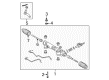
2007 Toyota Tundra Gear Assembly
Part Number: 44250-0C160$556.03 MSRP: $814.86You Save: $258.83 (32%)Ships in 1-3 Business DaysProduct Specifications- Other Name: Gear Assembly, Power Steering; Rack and Pinion Assembly; Steering Gearbox; Steering Gear Assembly
- Replaces: 44250-0C070, 44250-0C100
- Item Weight: 37.50 Pounds
- Item Dimensions: 51.5 x 11.3 x 9.5 inches
- Condition: New
- SKU: 44250-0C160
- Warranty: This genuine part is guaranteed by Toyota's factory warranty.
2007 Toyota Tundra Rack And Pinion
Looking for affordable OEM 2007 Toyota Tundra Rack And Pinion? Explore our comprehensive catalogue of genuine 2007 Toyota Tundra Rack And Pinion. All our parts are covered by the manufacturer's warranty. Plus, our straightforward return policy and speedy delivery service ensure an unparalleled shopping experience. We look forward to your visit!
2007 Toyota Tundra Rack And Pinion Parts Q&A
- Q: How to service and repair the power Rack And Pinion on 2007 Toyota Tundra?A: Power steering rack and pinion repair and servicing start with disconnecting the battery cable's negative terminal but require the wheel steering adjustment and wheel alignment completion before activating the steering angle sensor to maintain proper alignment. The battery cable needs 90 seconds of waiting time after ignition switch deactivation because some systems initiate their operations when reconnected. First position both front wheels forward before removing the wheels then unfastening the No.1 engine under cover. The service technician should first perform No. 2 intermediate shaft assembly separation before removing the LH tie rod end sub-assembly using Special Service Tool: 09628-00011 to disconnect it from the steering knuckle. Proper care must be taken to avoid damaging the front disc brake dust cover, ball joint dust cover or steering knuckle components. The same step should be executed to unbolt the tie rod end sub-assembly RH. Users must remove both return and pressure feed tubes by employing Special Service Tool: 09023-12701 through the pressure feed tube assembly disconnect points before discharging the pressure feed tube clamp. Separate the power steering rack and pinion assembly from the rest of the assembly by deleting its two bolts and two nuts with caution against rotating the nut during bolt removal. You must use Special Service Tool: 09612-00012 to secure the power steering rack and pinion during disassembly before taking out the tie rod end sub-assemblies LH and RH along with marking their original positions. Start by removing steering rack boot clips then successively take off the No. 2 steering rack boot followed by the No. 1 steering rack boot. You should inspect the tie rod end sub-assemblies LH and RH to check their torque level before making replacements if necessary. To check the total preload measure the steering rack ends when using Special Service Tool: 09616-00011 to fully rotate the power steering rack and pinion after temporarily installing the steering rack ends. Reassemble the power steering rack and pinion through tool 09612-00012 before booting up the No. 2 steering rack with silicone grease and repeating the same boot installation method for the No. 1 steering rack. Tighten the No. 2 steering rack boot clamps with Special Service Tool: 09521-24010 until the standard clearance reaches 3.0 mm or less before securing the boot clips. Fasten the tie rod end sub-assemblies LH and RH by aligning their matchmarks and tightening the lock nut to 69 Nm. Torque the two power steering rack and pinion assembly bolts to 120 Nm while connecting the pressure feed tube assembly according to specification on both sides. Connect the tie rod end sub-assembly LH and RH, and the No. 2 steering intermediate shaft sub-assembly and tighten with a torque of 35 Nm. The procedure concludes with reinstallation of front wheels followed by No. 1 engine under cover installation and reconnecting the negative battery terminal and bleeding power steering fluid and checking for leaks while confirming straight front wheels and correcting wheel alignment if necessary.
Related 2007 Toyota Tundra Parts
 2007 Toyota Tundra Steering Wheel
 2007 Toyota Tundra Power Steering Pump
 2007 Toyota Tundra Power Steering Hose
 2007 Toyota Tundra Steering Column
 2007 Toyota Tundra Drag Link
 2007 Toyota Tundra Power Steering Reservoir
 2007 Toyota Tundra Rack and Pinion Boot
 2007 Toyota Tundra Shift Interlock Solenoid
 2007 Toyota Tundra Steering Angle Sensor
 2007 Toyota Tundra Steering Column Cover
 2007 Toyota Tundra Steering Shaft
 2007 Toyota Tundra Tie Rod End