×
ToyotaParts- Hello
- Login or Register
- Quick Links
- Live Chat
- Track Order
- Parts Availability
- RMA
- Help Center
- Contact Us
- Shop for
- Toyota Parts
- Scion Parts
My Garage
My Account
Cart
OEM 2004 Toyota Tundra Rack And Pinion
Steering Rack And Pinion- Select Vehicle by Model
- Select Vehicle by VIN
Select Vehicle by Model
orMake
Model
Year
Select Vehicle by VIN
For the most accurate results, select vehicle by your VIN (Vehicle Identification Number).
3 Rack And Pinions found

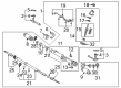
2004 Toyota Tundra Rack, Front
Part Number: 44204-0C011$580.43 MSRP: $850.63You Save: $270.20 (32%)Ships in 1-3 Business DaysProduct Specifications- Other Name: Rack Sub-Assembly, Power; Rack And Pinion Rack Gear, Front; Steering Gearbox; Steering Rack; Rack Sub-Assembly, Power Steering
- Position: Front
- Part Name Code: 44204
- Item Weight: 5.70 Pounds
- Item Dimensions: 32.1 x 3.3 x 2.8 inches
- Condition: New
- Fitment Type: Direct Replacement
- SKU: 44204-0C011
- Warranty: This genuine part is guaranteed by Toyota's factory warranty.

2004 Toyota Tundra Steering Gear
Part Number: 44250-0C041$722.76 MSRP: $1059.21You Save: $336.45 (32%)Product Specifications- Other Name: Gear Assembly, Power Steering; Rack and Pinion Assembly; Steering Gearbox; Rack & Pinion; Gear Assembly; Gear Assembly, Power Steering(For Rack & Pinion)
- Manufacturer Note: W(REAR STABILIZER)
- Replaces: 44250-0C050, 44250-0C020
- Part Name Code: 44250
- Item Weight: 1.40 Pounds
- Item Dimensions: 3.4 x 3.2 x 3.5 inches
- Condition: New
- Fitment Type: Direct Replacement
- SKU: 44250-0C041
- Warranty: This genuine part is guaranteed by Toyota's factory warranty.
2004 Toyota Tundra Steering Gear
Part Number: 44250-0C030$653.07 MSRP: $957.08You Save: $304.01 (32%)Product Specifications- Other Name: Gear Assembly, Power Steering; Rack and Pinion Assembly; Steering Gearbox; Rack & Pinion; Gear Assembly; Gear Assembly, Power Steering(For Rack & Pinion)
- Part Name Code: 44250
- Item Weight: 31.00 Pounds
- Item Dimensions: 56.0 x 11.2 x 7.1 inches
- Condition: New
- Fitment Type: Direct Replacement
- SKU: 44250-0C030
- Warranty: This genuine part is guaranteed by Toyota's factory warranty.
2004 Toyota Tundra Rack And Pinion
Looking for affordable OEM 2004 Toyota Tundra Rack And Pinion? Explore our comprehensive catalogue of genuine 2004 Toyota Tundra Rack And Pinion. All our parts are covered by the manufacturer's warranty. Plus, our straightforward return policy and speedy delivery service ensure an unparalleled shopping experience. We look forward to your visit!
2004 Toyota Tundra Rack And Pinion Parts Q&A
- Q: How to disassemble the Rack And Pinion on 2004 Toyota Tundra?A: Keep the rack and pinion vise from getting too tight when you attempt the disassembly procedure. Begin by using SST 09023-12700 with turn pressure tubes to remove 4 O-rings along with the tubes themselves. Secure the Rack And Pinion assembly by utilizing a vise along with SST 09612-00012 and two bolts (90105-10346) and nuts (90170-10198). Before removal, note down position marks for the tie rod end and lock nut and rack end. Then unscrew the lock nut and take out the tie rod end from both sides. Use a screwdriver to loosen the 2 clamps before removing the 2 clips and boots by marking the RH and LH boots without damaging their condition. Use a screwdriver and hammer to remove the washer while protecting the rack and pinion. Apply a spanner to hold the rack before taking off the rack end with SST 09922-10010 by marking both right and left rack ends. Start by disassembling the rack guide spring cap lock nut with SST 09922-10010. After that, use a hexagon wrench to take away the rack guide spring cap and rack guide spring and rack guide in sequence. Use SST 09816-30010 to take off the rack housing cap followed by the use of SST 09616-00011 to prevent the control valve shaft rotation to remove the self-locking nut. Use matchmarks on the control valve housing before removing the gasket and control valve assembly together with the dust cover. The valve shaft needs vinyl tape around it before pressing out the valve assembly with its oil seal and positioning a shop rag between blocks and the valve housing. Using SST 09631-16010 remove the control valve wire by turning the cylinder stop clockwise until the wire becomes visible followed by counterclockwise rotation to extract it. To remove the bushing and O-ring from the rack and pinion you should first utilize SST 09950-70010 (09951-07200) for pressing operations followed by removeriation of the bushing and O-ring before applying SST 09950-60010 (09951-00360), 09950-70010 (09951-07360) to extract the oil seal. Inspection of the rack and pinion must verify that its maximum runout is less than 0.03 mm (0.0118 inch) and check the teeth for wear and the back surface for damage. For proper installation of the oil seal and bearing use SST 09950-60010 (09951-00250) and SST 09950-70010 (09951-07150) to remove the components from the control valve housing followed by application of power steering fluid on the new oil seal lip before pressing it in with SST 09950-60010 (09951-00180, 09951-00320, 09952-06010) and SST 09950-70010 (09951-07150). Install the new bearing into position after coating it with molybdenum disulfide lithium base grease through the application of SST 09950-60010 (09951-00340), 09950-70010 (09951-07150). To replace two bearings you should press them out with SST 09950-60010 (09951-00260), 09950-70010 (09951-07150) before coating new bearings with grease and pressing them in with SST 09950-60010 (09951-00310), 09950-70010 (09951-07150) and SST 09950-60010 (09951-00320), 09950-70010 (09951-07150). For replacing the oil seal from the bushing use SST 09527-20011, 09612-24014 (09613-22011) while coating a new oil seal lip with power steering fluid before pressing it in with SST 09950-60010 (09951-00300, 09951-00460, 09952-06010). Install the new teflon ring and O-ring by first removing the existing components from the rack and pinion then coating an O-ring with power steering fluid before expansion of the teflon ring which also receives fluid coating before installation. Implement teflon ring replacement by removing 4 teflon rings from the control valve assembly then expanding 4 new rings before coating them with fluid before installation while executing the tapered end of SST 09631-20081 over the rings carefully. Reassembly requires parts marked with arrows to receive a coating of power steering fluid or molybdenum disulfide lithium base grease and the installation of the oil seal with a new lip that has been coated in fluid utilizing SST 09950-60010 (09951-00330, 09951-00490, 09952-06010), 09950-70010 (09951-07360) while maintaining the correct direction. When assembling the rack and pinion use SST 09631-20051 while coating it with fluid while also maintaining care for the oil seal lip. Begin installation of the bushing after applying new O-rings with fluid applied to them while maintaining correct direction and protecting the oil seal lip. The installation hole for the cylinder end stopper wire should be lines up with the rack housing slot. Then insert a new wire and turn the stopper with SST 09631-16010 in a clockwise direction 450 ± 50°. To conduct the air tightness test install SST 09631-12071 while applying a vacuum of 53 kPa (400 mm Hg 15.75 inch Hg) for about 30 seconds and examine the variations in vacuum pressure. Install the control valve assembly while protecting the oil seal lip with vinyl tape on the valve shaft and lubricating the teflon rings with fluid before a precise assembly installation. Place the oil seal inside SST 09612-22011 with its new lip coated with fluid while maintaining the correct orientation. Install the control valve housing together with the control valve assembly by placing a new gasket on the rack housing while aligning matchmarks before tightening 2 bolts to 18 Nm (185 kgf-cm, 13 ft. lbs.). The self-locking nut requires SST 09616-00011 for installation at a torque of 30 Nm (300 kgf-cm, 22 ft. lbs.). Apply sealant to 2 or 3 threads of the cap and install it along with SST 09816-30010 while staking the 2 parts of the cap and tightening to 59 Nm (600 kgf-cm, 43 ft. lbs.). Sealant goes onto 2 or 3 threads of the rack guide spring cap before installing the rack guide, rack guide spring with final placement of the rack guide spring cap. Adjust total preload through these steps where you install temporarily the RH and LH rack ends, install the rack guide spring cap with 25 Nm torque (250 kgf-cm / 18 ft. lbs.), return the cap to 12° position and use SST 09616-00011 to turn the control valve shaft while tightening the cap to achieve preload specifications (1.0 - 1.45 Nm / 10 - 14.5 kgf-cm / 8.7 - 12.6 inch lbs.) after loosening the cap until the spring stops functioning. Apply sealant to 2 or 3 threads of the rack guide spring cap lock nut before temporarily installing it followed by torque application with SST 09922-10010 to 51 Nm (520 kgf-cm, 38 ft. lbs.) while rechecking the total preload. The last procedure involves ensuring correct placement of the claw washer relative to rack and pinion grooves before torquing the rack end with SST 09922-10010 to 76 Nm (770 kgf-cm, 56 ft. lbs.) and then staking the washer on each side. The RH and LH rack boots require proper installation by running a new clamp into the grooves then carefully placing the boot before tightening the clamp with SST 09521-24010 and adding the clip. Reinstall the clip for the opposite side. Relationship of matchmarks must be lined up when installing RH and LH tie rod ends followed by a toe-in adjustment before torquing the lock nut to 55 Nm (560 kgf-cm, 41 ft. lbs.). The installation requires 2 turn pressure tubes with power steering fluid applied to 4 new O-rings then insertion with SST 09023-12700 before torquing to 12 Nm (117 kgf-cm, 9 ft. lbs.).
Related 2004 Toyota Tundra Parts
 2004 Toyota Tundra Steering Wheel
 2004 Toyota Tundra Power Steering Pump
 2004 Toyota Tundra Power Steering Hose
 2004 Toyota Tundra Drag Link
 2004 Toyota Tundra Power Steering Control Valve
 2004 Toyota Tundra Power Steering Reservoir
 2004 Toyota Tundra Rack and Pinion Boot
 2004 Toyota Tundra Steering Angle Sensor
 2004 Toyota Tundra Steering Column Cover
 2004 Toyota Tundra Steering Gear Box
 2004 Toyota Tundra Steering Shaft
 2004 Toyota Tundra Tie Rod End