×
ToyotaParts- Hello
- Login or Register
- Quick Links
- Live Chat
- Track Order
- Parts Availability
- RMA
- Help Center
- Contact Us
- Shop for
- Toyota Parts
- Scion Parts
My Garage
My Account
Cart
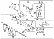
OEM 2005 Toyota Tundra Rack And Pinion
Steering Rack And Pinion- Select Vehicle by Model
- Select Vehicle by VIN
Select Vehicle by Model
orMake
Model
Year
Select Vehicle by VIN
For the most accurate results, select vehicle by your VIN (Vehicle Identification Number).
3 Rack And Pinions found

2005 Toyota Tundra Rack, Front
Part Number: 44204-0C011$580.43 MSRP: $850.63You Save: $270.20 (32%)Ships in 1-3 Business DaysProduct Specifications- Other Name: Rack Sub-Assembly, Power; Rack And Pinion Rack Gear, Front; Steering Gearbox; Steering Rack; Rack Sub-Assembly, Power Steering
- Position: Front
- Part Name Code: 44204
- Item Weight: 5.70 Pounds
- Item Dimensions: 32.1 x 3.3 x 2.8 inches
- Condition: New
- Fitment Type: Direct Replacement
- SKU: 44204-0C011
- Warranty: This genuine part is guaranteed by Toyota's factory warranty.

2005 Toyota Tundra Steering Gear
Part Number: 44250-0C041$722.76 MSRP: $1059.21You Save: $336.45 (32%)Product Specifications- Other Name: Gear Assembly, Power Steering; Rack and Pinion Assembly; Steering Gearbox; Rack & Pinion; Gear Assembly; Gear Assembly, Power Steering(For Rack & Pinion)
- Manufacturer Note: W(REAR STABILIZER)
- Replaces: 44250-0C050, 44250-0C020
- Part Name Code: 44250
- Item Weight: 1.40 Pounds
- Item Dimensions: 3.4 x 3.2 x 3.5 inches
- Condition: New
- Fitment Type: Direct Replacement
- SKU: 44250-0C041
- Warranty: This genuine part is guaranteed by Toyota's factory warranty.
2005 Toyota Tundra Steering Gear
Part Number: 44250-0C030$653.07 MSRP: $957.08You Save: $304.01 (32%)Product Specifications- Other Name: Gear Assembly, Power Steering; Rack and Pinion Assembly; Steering Gearbox; Rack & Pinion; Gear Assembly; Gear Assembly, Power Steering(For Rack & Pinion)
- Part Name Code: 44250
- Item Weight: 31.00 Pounds
- Item Dimensions: 56.0 x 11.2 x 7.1 inches
- Condition: New
- Fitment Type: Direct Replacement
- SKU: 44250-0C030
- Warranty: This genuine part is guaranteed by Toyota's factory warranty.
2005 Toyota Tundra Rack And Pinion
Looking for affordable OEM 2005 Toyota Tundra Rack And Pinion? Explore our comprehensive catalogue of genuine 2005 Toyota Tundra Rack And Pinion. All our parts are covered by the manufacturer's warranty. Plus, our straightforward return policy and speedy delivery service ensure an unparalleled shopping experience. We look forward to your visit!
2005 Toyota Tundra Rack And Pinion Parts Q&A
- Q: How to disassemble the power Rack And Pinion on 2005 Toyota Tundra?A: The power rack and pinion disassembly process starts with turning pressure tubes removal through Special Service Tool: 09023-38401 followed by extracting four O-rings from these tubes. Secure the PS rack and pinion assembly inside a vise through the use of Special Service Tool: 09612-00012 with 2 bolts (90105-10346) and nuts (90170-10198). Before loosening start by marking all parts of the tie rod end and rack end with lock nut. Disassemble the tie rod end and lock nut on each side. Loosen the 2 clamps which can be done with a screwdriver to extract the 2 clips and boots from their positions while taking care to maintain boot integrity. Using a screwdriver with a hammer gently unstake the washer from each RH and LH rack end before using a spanner to remove them with Special Service Tool: 09922-10010 while recording which end belongs to which side. Disassemble the washer from the rack end before moving on to the other side. Begin the process by using Special Service Tool: 09922-10010 to detach the rack guide spring cap lock nut. Then proceed with a hexagon wrench to loosen the rack guide spring cap before the rack guide spring and rack guide. The technician must remove the rack housing cap with Special Service Tool: 09816-30010 before stopping control valve shaft rotation with Special Service Tool: 09616-00011 to extract the self-locking nut. Begin by marking the control valve housing together with the rack housing and then remove the 2 mounting bolts for the control valve housing assembly. The final steps before removing the gasket from the rack housing will be removing both housing components with their control valve assembly. The valve shaft must have vinyl tape around its serrated section to secure the oil seal lip while using the valve assembly press against the control valve housing. A shop rag should be placed between blocks to catch the assembly. After removing the oil seal from the control valve assembly, the Special Service Tool: 09631-16010 allows for turning the cylinder end stopper clockwise until the wire end becomes visible before counterclockwise wire removal. To end the process press the rack and pinion with the bushing by using Special Service Tool: 09950-70010 (09951-07200) but maintain rack safety at all times while removing the bushing with its O-ring and using Special Service Tool: 09950-60010 (09951-00360) and 09950-70010 (09951-07360) to press out the oil seal.
Related 2005 Toyota Tundra Parts
 2005 Toyota Tundra Steering Wheel
 2005 Toyota Tundra Power Steering Pump
 2005 Toyota Tundra Power Steering Hose
 2005 Toyota Tundra Drag Link
 2005 Toyota Tundra Power Steering Control Valve
 2005 Toyota Tundra Power Steering Reservoir
 2005 Toyota Tundra Rack and Pinion Boot
 2005 Toyota Tundra Steering Angle Sensor
 2005 Toyota Tundra Steering Column Cover
 2005 Toyota Tundra Steering Gear Box
 2005 Toyota Tundra Steering Shaft
 2005 Toyota Tundra Tie Rod End