×
ToyotaParts- Hello
- Login or Register
- Quick Links
- Live Chat
- Track Order
- Parts Availability
- RMA
- Help Center
- Contact Us
- Shop for
- Toyota Parts
- Scion Parts
My Garage
My Account
Cart
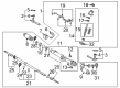
OEM 2003 Toyota Tundra Rack And Pinion
Steering Rack And Pinion- Select Vehicle by Model
- Select Vehicle by VIN
Select Vehicle by Model
orMake
Model
Year
Select Vehicle by VIN
For the most accurate results, select vehicle by your VIN (Vehicle Identification Number).
3 Rack And Pinions found

2003 Toyota Tundra Rack, Front
Part Number: 44204-0C011$580.43 MSRP: $850.63You Save: $270.20 (32%)Ships in 1-3 Business DaysProduct Specifications- Other Name: Rack Sub-Assembly, Power; Rack And Pinion Rack Gear, Front; Steering Gearbox; Steering Rack; Rack Sub-Assembly, Power Steering
- Position: Front
- Part Name Code: 44204
- Item Weight: 5.70 Pounds
- Item Dimensions: 32.1 x 3.3 x 2.8 inches
- Condition: New
- Fitment Type: Direct Replacement
- SKU: 44204-0C011
- Warranty: This genuine part is guaranteed by Toyota's factory warranty.

2003 Toyota Tundra Steering Gear
Part Number: 44250-0C041$722.76 MSRP: $1059.21You Save: $336.45 (32%)Product Specifications- Other Name: Gear Assembly, Power Steering; Rack and Pinion Assembly; Steering Gearbox; Rack & Pinion; Gear Assembly; Gear Assembly, Power Steering(For Rack & Pinion)
- Manufacturer Note: W(REAR STABILIZER)
- Replaces: 44250-0C050, 44250-0C020
- Part Name Code: 44250
- Item Weight: 1.40 Pounds
- Item Dimensions: 3.4 x 3.2 x 3.5 inches
- Condition: New
- Fitment Type: Direct Replacement
- SKU: 44250-0C041
- Warranty: This genuine part is guaranteed by Toyota's factory warranty.
2003 Toyota Tundra Steering Gear
Part Number: 44250-0C030$653.07 MSRP: $957.08You Save: $304.01 (32%)Product Specifications- Other Name: Gear Assembly, Power Steering; Rack and Pinion Assembly; Steering Gearbox; Rack & Pinion; Gear Assembly; Gear Assembly, Power Steering(For Rack & Pinion)
- Part Name Code: 44250
- Item Weight: 31.00 Pounds
- Item Dimensions: 56.0 x 11.2 x 7.1 inches
- Condition: New
- Fitment Type: Direct Replacement
- SKU: 44250-0C030
- Warranty: This genuine part is guaranteed by Toyota's factory warranty.
2003 Toyota Tundra Rack And Pinion
Looking for affordable OEM 2003 Toyota Tundra Rack And Pinion? Explore our comprehensive catalogue of genuine 2003 Toyota Tundra Rack And Pinion. All our parts are covered by the manufacturer's warranty. Plus, our straightforward return policy and speedy delivery service ensure an unparalleled shopping experience. We look forward to your visit!
2003 Toyota Tundra Rack And Pinion Parts Q&A
- Q: How to service and repair the Rack And Pinion on 2003 Toyota Tundra?A: Usage of Special Service Tool: 09023-12700 lets you remove the 2 turn pressure tubes followed by removing the 4 O-rings. The Rack and Pinion assembly needs to be fixed in a vise through the use of Special Service Tool: 09612-00012 which includes 2 bolts (90105-10346) and nuts (90170-10198). Record all positions of tie rod ends along with lock nuts and rack ends before unfastening them. The service technician should loosen the 2 clamps while removing RH and LH clips and rack boots and clamps without damaging the boots. Remove the claw washers from their position using a screwdriver in combination with a hammer when holding the rack and pinion with a spanner and employing Special Service Tool: 09922-10010 to extract the rack ends followed by washing. Complete the removal sequence of the rack guide spring cap lock nut using Special Service Tool: 09922-10010 and proceed with extracting the rack guide spring cap and rack guide spring and rack guide using a hexagon wrench. Professional tools 09816-30010 enable removal of the rack housing cap while tool 09616-00011 enables control valve shaft rotation restriction for removal of the self-locking nut and dust cover. Attach matchmarks to the control valve housing and rack housing before removing the control valve housing with control valve assembly then stripping the gasket. The valve shaft requires vinyl tape wrapping before the valve assembly extraction with its oil seal. The block and valve housing separation should involve a shop rag positioned between these parts. To remove the wire from the cylinder end stopper use Special Service Tool: 09631-16010 and turn the stopper clockwise until the wire end appears and then move counter-clockwise to extract the wire. The bushing along with the O-ring is removed from the rack and pinion after applying Special Service Tool: 09950-70010 (09951-07200) while pressing the rack. The oil seal requires positioning within Special Service Tool: 09950-60010 (09951-00360), 09950-70010 (09951-07360) to complete the press-out operation. Inspect each rack and pinion for accidents, misalignment runout exceeding 0.03 mm (0.0118 inch) while checking for tooth deterioration. First coat the new oil seal lip with power steering fluid before pressing it into position using Special Service Tool: 09950-60010 (09951-00180, 09951-00320, 09952-06010). The necessary tool for bearing removal and installation is Special Service Tool: 09950-60010 (09951-00260). The oil seal should be changed from the bushing using Special Service Tool: 09527-20011, 09612-24014 (09613-22011) while avoiding damage to the bushing structure. Before installing the new O-ring the technician coats it with power steering fluid and then replaces the teflon ring and O-ring from the rack and pinion. Place four teflon rings from the control valve assembly into tank solutions to expand them before coating them with power steering fluid during their accurate installation. Installation of the oil seal requires Special Service Tool: 09950-60010 (09951-00330, 09951-00490, 09952-06010) which needs to be used for the correct oil seal orientation and after applying power steering fluid or molybdenum disulfide lithium base grease to the mentioned components. When installing the rack and pinion together with its bushing use power steering fluid to protect the oil seal lip from damage. Before continuing, conduct an air-tightness test using Special Service Tool: 09631-12071 for the cylinder end stopper installation. Also install the control valve assembly while avoiding damage to teflon rings and oil seal components. Use Special Service Tool: 09612-22011 to install the oil seal before mounting the control valve assembly on the valve housing with matched alignment and tightener two bolts to 18 Nm (185 kgf-cm, 13 ft. lbs.). Mount the self-locking nut with 30 Nm torque before you install the dust cover and rack housing cap which requires Part No. 08833-00080 or Three Bond 1344, Loctite 242 or equivalent sealant torqued to 59 Nm. Install the rack guide with its rack guide spring and rack guide spring cap while adjusting the total preload between 1.0 - 1.45 Nm (10 - 14.5 kgf-cm and 8.7 - 12.6 inch lbs.). Use sealant on the rack guide spring cap lock nut before tightening it to 51 Nm (520 kgf-cm, 38 ft. lbs.) and detach the RH and LH rack ends. The installation process requires torqueing the lock nut to 55 Nm (560 kgf-cm, 41 ft. lbs.) followed by torqueing the 2 turn pressure tubes at 12 Nm (117 kgf-cm, 9 ft. lbs.). These steps must be carried out with O-rings that received power steering fluid coating.
Related 2003 Toyota Tundra Parts
 2003 Toyota Tundra Steering Wheel
 2003 Toyota Tundra Power Steering Pump
 2003 Toyota Tundra Power Steering Hose
 2003 Toyota Tundra Drag Link
 2003 Toyota Tundra Power Steering Control Valve
 2003 Toyota Tundra Power Steering Reservoir
 2003 Toyota Tundra Rack and Pinion Boot
 2003 Toyota Tundra Steering Column Cover
 2003 Toyota Tundra Steering Gear Box
 2003 Toyota Tundra Steering Shaft
 2003 Toyota Tundra Tie Rod End
 2003 Toyota Tundra Wiper Switch