×
ToyotaParts- Hello
- Login or Register
- Quick Links
- Live Chat
- Track Order
- Parts Availability
- RMA
- Help Center
- Contact Us
- Shop for
- Toyota Parts
- Scion Parts
My Garage
My Account
Cart
OEM 2001 Toyota Tundra Rack And Pinion
Steering Rack And Pinion- Select Vehicle by Model
- Select Vehicle by VIN
Select Vehicle by Model
orMake
Model
Year
Select Vehicle by VIN
For the most accurate results, select vehicle by your VIN (Vehicle Identification Number).
2 Rack And Pinions found


 Product Specifications
- Other Name: Rack Sub-Assembly, Power; Rack And Pinion Rack Gear, Front; Steering Gearbox; Steering Rack; Rack Sub-Assembly, Power Steering
- Position: Front
- Part Name Code: 44204
- Item Weight: 5.40 Pounds
- Item Dimensions: 32.7 x 3.2 x 2.8 inches
- Condition: New
- Fitment Type: Direct Replacement
- SKU: 44204-0C010
- Warranty: This genuine part is guaranteed by Toyota's factory warranty.


2001 Toyota Tundra Steering Gear
Part Number: 44250-0C010$690.86 MSRP: $1012.47You Save: $321.61 (32%)Product Specifications- Other Name: Gear Assembly, Power Steering; Rack and Pinion Assembly; Steering Gearbox; Rack & Pinion; Gear Assembly; Gear Assembly, Power Steering(For Rack & Pinion)
- Part Name Code: 44250
- Item Weight: 30.70 Pounds
- Item Dimensions: 58.2 x 11.2 x 6.8 inches
- Condition: New
- Fitment Type: Direct Replacement
- SKU: 44250-0C010
- Warranty: This genuine part is guaranteed by Toyota's factory warranty.
2001 Toyota Tundra Rack And Pinion
Looking for affordable OEM 2001 Toyota Tundra Rack And Pinion? Explore our comprehensive catalogue of genuine 2001 Toyota Tundra Rack And Pinion. All our parts are covered by the manufacturer's warranty. Plus, our straightforward return policy and speedy delivery service ensure an unparalleled shopping experience. We look forward to your visit!
2001 Toyota Tundra Rack And Pinion Parts Q&A
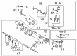
- Q: How can one effectively maintain a steering rack assembly using rack and pinion on 2001 Toyota Tundra?A: The first step of rack and pinion disassembly requires the use of Special Service Tool 09023-12700 to remove 2 turn pressure tubes and extract the 4 O-rings. Fasten the Rack And Pinion assembly within SST 09612-00012 through bolts 90105-10346 and nuts 90170-10198 to secure it while stabilized in the vise. Mark all components you will handle before unlatching the tie rod ends and rack ends as well as the lock nuts. The screwdriver should be applied to loosen the clamps to take out the clips and boots while preserving their integrity. Unstake the claw washers with a screwdriver and hammer before removing the rack ends from the rack and pinion using SST 09922-10010 while marking them appropriately. SST 09922-10010 allows you to remove three components from the rack guide system which begins with the rack guide spring cap lock nut followed by the rack guide spring cap before you remove the rack guide spring and rack guide. You need SST 09816-30010 to remove the rack housing cap while using SST 09616-00011 as a stopper that prevents control valve shaft rotation for self-locking nut retrieval. Start the process by removing the dust cover together with the control valve housing and control valve assembly while writing down the matchmarks and extracting the gasket. A proper application of vinyl tape around the valve shaft followed by using the oil seal to push out the valve assembly with a shop rag placed between the valve housing and blocks helps prevent damage to the oil seal lip. SST 09631-16010 is used to remove both the oil seal and cylinder end stopper through clockwise then counterclockwise movements. SST 09950-70010 (09951-07200) helps to press out the rack and pinion along with the bushing followed by removing both parts and O-ring. Press the oil seal from the rack and pinion using SST 09950-60010 (09951-00360) together with SST 09950-70010 (09951-07360). Check the rack and pinion for runout at 0.03 mm (0.0118 inch) maximum and examine teeth wear as well as possible damage. The procedure requires using SST 09950-60010 (09951-00250) to install new bearings but the oil seal lip must be coated with power steering fluid before inserting it with SST 09950-60010 (09951-00180, 09951-00320, 09952-06010). The installation of new bearings requires molybdenum disulfide lithium base grease application before using SST 09950-60010 (09951-00340), 09950-70010 (09951-07150) for pressing operations. There are two situations where you might replace 2 bearings that require you to use SST 09950-60010 (09951-00260), 09950-70010 (09951-07150) to press the bearings in after greasing them. Replace the oil seal from the bushing with SST 09527-20011, 09612-24014 (09613-22011) only if needed but protect the bushing from damage. Apply power steering fluid to the lip of a new oil seal before using SST 09950-60010 (09951-00300, 09951-00460, 09952-06010) to install it. Install the rack and pinion's teflon ring and O-ring while avoiding groove damage followed by O-ring power steering fluid coating and installation. Install a new teflon ring by expanding it first and then coat the ring with power steering fluid prior to assembling it. The control valve assembly needs its four teflon rings removed before expanding new rings that receive fluid coating for proper installation alongside careful SST 09631-20081 usage. Reassembly requires application of power steering fluid or molybdenum disulfide lithium base grease to the parts before installing the oil seal using SST 09950-60010 (09951-00330, 09951-00490, 09952-06010) while maintaining proper direction. Fit the rack and pinion by using SST 09631-20051 while applying power steering fluid to it then remove the SST. Proceed with installing the bushing which has received power steering fluid on its new O-ring before gently pushing in the bushing but protecting the oil seal lips from harm. Align the installation hole for the wire that controls the cylinder end stopper and set a new wire in place while rotating the stopper clockwise 450 ± 50 degrees by using SST 09631-16010. The air tightness check needs SST 09631-12071 to apply vacuum pressure of 53 kPa (400 mm Hg, 15.75 inch Hg) for 30 seconds before inspecting for any changes. Install the control valve assembly after protecting the oil seal lips from damage then apply power steering fluid to the teflon rings. Install and press SST 09612-22011 towards its designated direction through the oil seal. Mount the control valve housing together with the control valve assembly by matching the predefined marks and fasten it using 2 bolts which require 18 Nm (185 kgf-cm, 13 ft. lbs.) torque. Apply SST 09616-00011 self-locking nut installation while torquing to 30 Nm (300 kgf-cm, 22 ft. lbs.). Replace the dust cover and rack housing cap by sealing 2 or 3 threads with sealant then torquing to 59 Nm (600 kgf-cm, 43 ft. lbs.) using SST 09816-30010. Employ SST 09616-00011 to secure the rack guide and rack guide spring and rack guide spring cap after placing sealant on the threads and hitting the cap parts with a punch and hammer. The adjustment of total preload involves first installing the rack ends followed by tightening the rack guide spring cap to 25 Nm (250 kgf-cm, 18 ft. lbs.) while rotating it 12° before applying SST 09616-00011 to the control valve shaft. The technician should remove preload from the rack guide spring by adjusting the cap until the spring stops working. Then, they should tighten the cap to achieve total preload specs of 1.0 - 1.45 Nm (10 - 14.5 kgf-cm; 8.7 - 12.6 inch lbs.). Apply SST 09922-10010 to install the rack guide spring cap lock nut with sealant while torquing it to 51 Nm (520 kgf-cm, 38 ft. lbs.) and rechecking the resulting total preload. Yang provides instructions to install right-hand and left-hand claw washers along with rack ends after aligning the claws with rack and pinion grooves. The torque value must be 76 Nm (770 kgf-cm, 56 ft. lbs.) while using SST 09922-10010. The right-hand and left-hand rack boots must be installed with the clamps and clips while making sure the rack and pinion hole remains grease-free before tightening the clamp with SST 09521-24010 on both sides. After aligning matchmarks on the rack end install the lock nut along with tie rod end before torquing it to 55 Nm (560 kgf-cm, 41 ft. lbs.). Proceed to install the 2 turn pressure tubes and apply power steering fluid to 4 new O-rings which must be fitted using SST 09023-12700 while torquing the end-points to 12 Nm (117 kgf-cm, 9 ft. lbs.).
Related 2001 Toyota Tundra Parts
 2001 Toyota Tundra Steering Wheel
 2001 Toyota Tundra Power Steering Pump
 2001 Toyota Tundra Power Steering Hose
 2001 Toyota Tundra Drag Link
 2001 Toyota Tundra Power Steering Control Valve
 2001 Toyota Tundra Power Steering Reservoir
 2001 Toyota Tundra Rack and Pinion Boot
 2001 Toyota Tundra Steering Column Cover
 2001 Toyota Tundra Steering Gear Box
 2001 Toyota Tundra Steering Shaft
 2001 Toyota Tundra Tie Rod End
 2001 Toyota Tundra Wiper Switch