×
ToyotaParts- Hello
- Login or Register
- Quick Links
- Live Chat
- Track Order
- Parts Availability
- RMA
- Help Center
- Contact Us
- Shop for
- Toyota Parts
- Scion Parts
My Garage
My Account
Cart
OEM Toyota RAV4 Rack And Pinion
Steering Gear- Select Vehicle by Model
- Select Vehicle by VIN
Select Vehicle by Model
orMake
Model
Year
Select Vehicle by VIN
For the most accurate results, select vehicle by your VIN (Vehicle Identification Number).
27 Rack And Pinions found


Toyota RAV4 Gear Assembly Part Number: 44200-42140
$644.19 MSRP: $944.07You Save: $299.88 (32%)Ships in 1-3 Business Days
Toyota RAV4 Steering Gear Part Number: 45510-0R041
$590.64 MSRP: $865.59You Save: $274.95 (32%)Ships in 1-3 Business Days
Toyota RAV4 Steering Gear Part Number: 44250-0R012
$699.72 MSRP: $1025.44You Save: $325.72 (32%)Ships in 1-3 Business Days
Toyota RAV4 Steering Gear Part Number: 45510-42230
$644.90 MSRP: $945.10You Save: $300.20 (32%)Ships in 1-2 Business DaysToyota RAV4 Steering Gear Part Number: 45510-42240
$672.70 MSRP: $985.85You Save: $313.15 (32%)Ships in 1-3 Business Days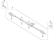
Toyota RAV4 Steering Gear Part Number: 44250-42170
$699.72 MSRP: $1025.44You Save: $325.72 (32%)Ships in 1-3 Business Days
Toyota RAV4 Steering Gear Part Number: 44200-42120
$770.65 MSRP: $1129.41You Save: $358.76 (32%)Ships in 1-3 Business DaysToyota RAV4 Steering Gear Part Number: 44250-0R013
$890.51 MSRP: $1305.05You Save: $414.54 (32%)Ships in 1-3 Business DaysToyota RAV4 Steering Gear Part Number: 44250-42190
$679.29 MSRP: $995.50You Save: $316.21 (32%)Ships in 1-3 Business DaysToyota RAV4 Steering Gear Part Number: 45510-42251
$568.96 MSRP: $833.82You Save: $264.86 (32%)Ships in 1-3 Business DaysToyota RAV4 Gear Assembly, Steering Part Number: 45510-78023
$590.64 MSRP: $865.59You Save: $274.95 (32%)Ships in 1-2 Business DaysToyota RAV4 Steering Gear Part Number: 45510-0R051
$590.64 MSRP: $865.59You Save: $274.95 (32%)Ships in 1-2 Business DaysToyota RAV4 Steering Gear Part Number: 44250-42200
$699.72 MSRP: $1025.44You Save: $325.72 (32%)Ships in 1-3 Business DaysToyota RAV4 Steering Gear Part Number: 44250-0R022
$699.72 MSRP: $1025.44You Save: $325.72 (32%)Ships in 1-3 Business DaysToyota RAV4 Steering Gear Part Number: 44250-0R023
$891.53 MSRP: $1306.55You Save: $415.02 (32%)Ships in 1-3 Business DaysToyota RAV4 Steering Gear Part Number: 44250-42800
$936.59 MSRP: $1372.58You Save: $435.99 (32%)Ships in 1-3 Business Days
Toyota RAV4 Rack, Front Part Number: 44204-42060
$322.10 MSRP: $459.89You Save: $137.79 (30%)Ships in 1-3 Business Days
Toyota RAV4 Rack, Front Part Number: 44204-42021
$322.10 MSRP: $459.89You Save: $137.79 (30%)Ships in 1-3 Business Days
Toyota RAV4 Gear Assembly, Power Steering(For Rack & Pinion) Part Number: 44250-42191
$970.07 MSRP: $1421.65You Save: $451.58 (32%)Ships in 1-2 Business DaysToyota RAV4 Gear Assembly, Power Steering(For Rack & Pinion) Part Number: 44250-0R150
$914.00 MSRP: $1339.48You Save: $425.48 (32%)Ships in 1-2 Business Days
| Page 1 of 2 |Next >
1-20 of 27 Results
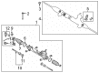
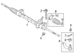
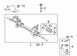
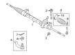
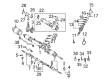
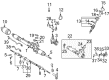
Toyota RAV4 Rack And Pinion
Choose genuine Rack And Pinion that pass strict quality control tests. You can trust the top quality and lasting durability. Shopping for OEM Rack And Pinion for your Toyota RAV4? Our website is your one-stop destination. We stock an extensive selection of genuine Toyota RAV4 parts. The price is affordable so you can save more. It only takes minutes to browse and find the exact fit. Easily add to cart and check out fast. Our hassle-free return policy will keep you stress-free. We process orders quickly for swift delivery. Your parts will arrive faster, so you can get back on the road sooner.
Toyota RAV4 Rack And Pinion Parts and Q&A
- Q: How to install the Rack And Pinion on Toyota RAV4?A:Begin rack and pinion installation by tightening the lock nut and No. 2 tie rod end sub-assembly onto the rack end until matchmarks line up, tighten the lock nut temporarily, and fully tighten it afterward for toe-in adjustment. The same process should follow for the No. 1 tie rod end sub-assembly. Use two bolts along with two nuts to mount the rack and pinion assembly on the front suspension crossmember through a 138 Nm torque (1407 kgf-cm and 102 ft-lbf) action while applying sufficient torque but keeping the nut stationary. Place the matchmarks in alignment before installing the intermediate shaft onto the rack and pinion while tightening it to 35 Nm (360 kgf-cm, 26 ft-lbf). The No. 1 steering column hole cover sub-assembly must be installed to the rack and pinion with a newly provided clamp. You should install the engine with transaxle for both the 2GR-FE and the 2AR-FE configurations. Fasten clip B to the body structure before installing the No. 1 hole cover through the use of clip A while verifying the integrity of the cover's lip. Place matchmarks correctly and fasten the sliding yoke to the intermediate shaft by torquing it to 35 Nm (360 kgf-cm, 26 ft-lbf). The silencer sheet for the column hole cover requires installation with two clips prior to installing the floor carpet. The steering knuckle will receive the No. 2 tie rod end sub-assembly by using the castle nut to produce a torque of 49 Nm (500 kgf-cm, 36 ft-lbf). Clip hole realignments will require an additional 60° nut torque. Follow the previous steps to install a new cotter pin, then repeat the method for the No. 1 tie rod end sub-assembly installation. Begin by installing front wheels while torquing them to 103 Nm (1,050 kgf-cm, 76 ft-lbf). The next step includes connecting the cable to the negative battery terminal followed by steering wheel positioning straight ahead. The sequence ends with front wheel alignment inspection and adjustment.
- Q: How to remove the Rack And Pinion on Toyota RAV4?A:A proper procedure to remove a rack and pinion begins with aligning front wheels directly ahead followed by negative battery cable removal and a minimum 90-second delay as a precaution against Air Bag pretensioner intervention. First position the wheels in a straight-ahead direction before taking off the No. 2 tie rod end sub-assembly through(cube) pin and castle nut removal. Complete this step by using Special Service Tool: 09628-62011 to disconnect the tie rod end from the steering knuckle without damaging the dust cover. Proceed with the same method to disconnect the No. 1 tie rod end sub-assembly. Begin the operation of removing the silencer sheet of the column hole cover by pulling out the floor carpet and two clips. The seat belt will hold the Steering Wheel into position before matchmarks are placed on the steering intermediate shaft sliding yoke. The bolt can then be removed and the sliding yoke disconnected. The No. 1 steering column hole cover detaches after A clip removal and separating B clip from the body. The engine assembly with transaxle needs removal to disconnect the column hole cover from the rack and pinion by unclamping it. Mark the intermediate rack and pinion shaft at two positions before removing its connecting bolt to separate the steering intermediate shaft. The rack and pinion assembly requires removal by dismounting its two bolts and two nuts which must not turn during the bolt-unfastening process from the suspension crossmember. Secure the rack and pinion assembly by using Special Service Tool: 09612-00012 but only when the tool is covered with protective tape and placed in a vise. Reapply the tool as required. Last, place matchmarks on both the No. 2 tie rod end sub-assembly and the rack end and take out the No. 2 tie rod end sub-assembly while using the same steps for the No. 1 tie rod end sub-assembly.

Related Toyota RAV4 Parts
 Toyota RAV4 Steering Wheel
 Toyota RAV4 Power Steering Pump
 Toyota RAV4 Power Steering Reservoir
 Toyota RAV4 Power Steering Control Valve
 Toyota RAV4 Power Steering Hose
 Toyota RAV4 Rack and Pinion Boot
 Toyota RAV4 Steering Angle Sensor
 Toyota RAV4 Steering Column
 Toyota RAV4 Steering Column Cover
 Toyota RAV4 Steering Gear Box
 Toyota RAV4 Steering Shaft
 Toyota RAV4 Tie Rod End