×
ToyotaParts- Hello
- Login or Register
- Quick Links
- Live Chat
- Track Order
- Parts Availability
- RMA
- Help Center
- Contact Us
- Shop for
- Toyota Parts
- Scion Parts
My Garage
My Account
Cart
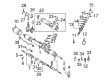
OEM 2003 Toyota RAV4 Rack And Pinion
Steering Rack And Pinion- Select Vehicle by Model
- Select Vehicle by VIN
Select Vehicle by Model
orMake
Model
Year
Select Vehicle by VIN
For the most accurate results, select vehicle by your VIN (Vehicle Identification Number).
2 Rack And Pinions found

2003 Toyota RAV4 Rack, Front
Part Number: 44204-42060$322.10 MSRP: $459.89You Save: $137.79 (30%)Ships in 1-3 Business DaysProduct Specifications- Other Name: Rack Sub-Assembly, Power; Rack And Pinion Rack Gear, Front; Steering Gearbox; Steering Rack; Rack Sub-Assembly, Power Steering
- Position: Front
- Part Name Code: 44204
- Item Weight: 5.50 Pounds
- Item Dimensions: 32.1 x 3.1 x 2.8 inches
- Condition: New
- Fitment Type: Direct Replacement
- SKU: 44204-42060
- Warranty: This genuine part is guaranteed by Toyota's factory warranty.

2003 Toyota RAV4 Steering Gear
Part Number: 44200-42120$770.65 MSRP: $1129.41You Save: $358.76 (32%)Ships in 1-3 Business DaysProduct Specifications- Other Name: Link Assembly, Power Steering; Rack and Pinion Assembly; Steering Gearbox; Rack & Pinion; Gear Assembly; Gear Assembly, Power Steering(For Rack & Pinion)
- Part Name Code: 44250
- Item Weight: 16.40 Pounds
- Item Dimensions: 49.2 x 10.4 x 6.6 inches
- Condition: New
- Fitment Type: Direct Replacement
- SKU: 44200-42120
- Warranty: This genuine part is guaranteed by Toyota's factory warranty.
2003 Toyota RAV4 Rack And Pinion
Looking for affordable OEM 2003 Toyota RAV4 Rack And Pinion? Explore our comprehensive catalogue of genuine 2003 Toyota RAV4 Rack And Pinion. All our parts are covered by the manufacturer's warranty. Plus, our straightforward return policy and speedy delivery service ensure an unparalleled shopping experience. We look forward to your visit!
2003 Toyota RAV4 Rack And Pinion Parts Q&A
- Q: How to disassemble the Rack And Pinion on 2003 Toyota RAV4?A: A proper start for disassembling the rack and pinion demands that you should not strain the vise beyond a reasonable limit. You will use tool SST 09023-38200 to remove both pressure tubes that have 2 turns of thread. Set the Rack And Pinion assembly inside the vise with SST 09612-00012. Mark both RH and LH tie rod ends before they are removed with their corresponding lock nuts by starting with a locked nut loosening and then removing the ends and lock nuts and repeating the process on the other tie rod end. Use a clamp screw to remove the RH and LH clips and clamps and rack boots without damaging the boot while marking the RH and LH rack boots. When removing the rack ends, users should begin by unstaking the claw washer with a screwdriver and a hammer while avoiding rack and pinion damage. Next, they should secure the rack and pinion with a 22 mm spanner and detach the rack end using SST 09922-10010 and remove the claw washer before repeating these steps for the opposite side. Marking the RH and LH rack ends will identify both sides. The removal process begins with matchmarking the bracket along with its bolt before they are extracted from the No. 1 rack housing bracket. The final step involves removing the grommet. Apply SST 09922-10010 on the rack guide spring cap lock nut to remove it before taking out the rack guide spring cap and rack guide spring and conical spring and rack guide with a 21 mm hexagon wrench. Use SST 09616-00011 to remove the rack and pinion housing cap together with its self-locking nut as a way to stop control valve shaft rotation. Disassemble the control valve assembly and upper oil seal and upper bearing by using snap ring pliers together with SST 09613-12010 while avoiding hit forces on the control valve. Use snap ring pliers to take out the cylinder end stopper followed by removing the rack and pinion and oil seal through the implementation of a brass bar. The inspection of the rack and pinion includes checking for runout as well as teeth wear and damage alongside examining the back surface for signs of wear and damage and requiring replacement as needed. Check dimensions of the control valve assembly along with its bushing then replace defective components if needed. To replace the lower bearing of the control valve shaft one must tap it out using a brass bar and hammer then coat a new bearing with molybdenum disulfide lithium base grease before installing it into the rack housing. Workers should exploit SST 09950-60010 (09951-00260) to squeeze out the oil seal from the rack housing control valve shaft assembly side before applying power steering fluid to new oil seal lips and inserting them with SST 09950-60010 (09951-00230, 09951-00400, 09952-06010). Use the SST 09612-24014 (09613-22011) tools to replace the control valve assembly bushing and lower oil seal while avoiding damages to the rack housing. The oil seal will be pressed out by using a screwdriver after proper precautions against rack housing damage are taken. Place new oil seal lips into power steering fluid and insert them with SST 09950-60010 (09951-00230 and 09951-00340 or 09952-06010) and SST 09950-60010 (09951-00280 or 09951-00350 or 09952-06010). Replace the rack and pinion Teflon ring and O-ring by first removing them with a screwdriver followed by lubricating a new O-ring with power steering fluid before expanding and installing the new Teflon ring while taking care to avoid damaging the groove structure. The Teflon rings of the control valve assembly must first be removed with a screwdriver then new rings need expansion before coating them with power steering fluid while maintaining Teflon rings in safe condition. Install 2 new union seats through an extension bar and hammer while removing all dust to protect the assembly. The process of reassembly requires rack and pinion installation using SST 09631-16020 followed by power steering fluid coating afterwards the rack housing installation before removing the SST tool. Install the parts using power steering fluid or molybdenum disulfide lithium base grease. Place vinyl tape first around the rack and pinion end and fill the opening with power steering fluid while making sure the oil seal faces the right direction when installed. Insert SST 09612-22011 into the cylinder end stopper before putting a new snap ring into place. A third-party air tightness tester should apply 53 kPa (400 mmHg, 15.75 inch Hg) vacuum pressure for 30 seconds for vacuum leak detection evaluation. The control valve assembly should be installed into the rack housing and then a new upper bearing should be press-fit using SST 09612-22011 with molybdenum disulfide lithium base grease application before press-fitting a new upper oil seal that has been coated with power steering fluid while using its new snap ring. Proceed with the installation of a new self-locking nut after stopping the control valve shaft rotation through the use of SST 09616-00011. The torque should be set to 12 Nm (125 kgf-cm, 9 ft. lbs.), measure dimension "A" with SST 09613-12020, then stake the self-locking nut. Apply three bond 1344 (part no. 08833-00080) or equivalent sealant to the rack housing cap before torquing it to 69 Nm (700 kgf-cm, 51 ft. lbs.). First prepare the rack guide followed by installation of conical spring, rack guide spring and finally the rack guide spring cap with right-hand orientation while applying sealant to the rack guide spring cap. First adjust the total preload by installing temporary RH and LH rack ends while torquing the rack guide spring cap to 25 Nm (250 kgf-cm, 18 ft. lbs.) before returning it to 12 degrees then rotating the control valve shaft followed by relaxation of the rack guide spring cap until it lost function and its final tightening to achieve the specification range of preload (1.1 - 1.6 Nm, 11 - 16 kgf-cm, 9.7 - 14.2 inch lbs.). Install the rack guide spring cap lock nut onto its seat using SST 09922-10011 and sealant before torquing the assembly to 32 Nm (330 kgf-cm, 24 ft. lbs.). The total preload should then be rechecked. The RH and LH rack ends must be removed before installing new rack ends and claw washers. Proper alignment should be performed with the rack and pinion grooves before torquing the rack end to 60 Nm with SST 09922-10010 and staking the washer. Proceed by installing the No. 1 rack housing bracket with its grommet and then torque the bolt to 61 Nm (620 kgf-cm, 45 ft. lbs.). After that, install RH and LH rack boots with clamps and clips while ensuring the rack and pinion hole remains free from grease and ensure the clamp is tightly fastened without damaging the boot. Repeat the installation process on the other side and finish by installing 2 turn pressure tubes with SST 09023-38200 at 27 Nm (270 kgf-cm, 20 ft. lbs.).
Related 2003 Toyota RAV4 Parts
 2003 Toyota RAV4 Steering Wheel
 2003 Toyota RAV4 Ignition Switch
 2003 Toyota RAV4 Power Steering Pump
 2003 Toyota RAV4 Power Steering Reservoir
 2003 Toyota RAV4 Drag Link
 2003 Toyota RAV4 Power Steering Control Valve
 2003 Toyota RAV4 Power Steering Hose
 2003 Toyota RAV4 Rack and Pinion Boot
 2003 Toyota RAV4 Steering Column Cover
 2003 Toyota RAV4 Steering Gear Box
 2003 Toyota RAV4 Steering Shaft
 2003 Toyota RAV4 Tie Rod End