×
ToyotaParts- Hello
- Login or Register
- Quick Links
- Live Chat
- Track Order
- Parts Availability
- RMA
- Help Center
- Contact Us
- Shop for
- Toyota Parts
- Scion Parts
My Garage
My Account
Cart
OEM 2004 Toyota RAV4 Rack And Pinion
Steering Rack And Pinion- Select Vehicle by Model
- Select Vehicle by VIN
Select Vehicle by Model
orMake
Model
Year
Select Vehicle by VIN
For the most accurate results, select vehicle by your VIN (Vehicle Identification Number).
1 Rack And Pinion found


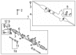
2004 Toyota RAV4 Gear Assembly
Part Number: 44200-42140$644.19 MSRP: $944.07You Save: $299.88 (32%)Ships in 1-3 Business DaysProduct Specifications- Other Name: Rack and Pinion Assembly; Steering Gearbox; Rack & Pinion; Link Assembly, Power Steering
- Part Name Code: 44200
- Item Weight: 15.80 Pounds
- Item Dimensions: 51.2 x 10.6 x 6.9 inches
- Condition: New
- Fitment Type: Direct Replacement
- SKU: 44200-42140
- Warranty: This genuine part is guaranteed by Toyota's factory warranty.
2004 Toyota RAV4 Rack And Pinion
Looking for affordable OEM 2004 Toyota RAV4 Rack And Pinion? Explore our comprehensive catalogue of genuine 2004 Toyota RAV4 Rack And Pinion. All our parts are covered by the manufacturer's warranty. Plus, our straightforward return policy and speedy delivery service ensure an unparalleled shopping experience. We look forward to your visit!
2004 Toyota RAV4 Rack And Pinion Parts Q&A
- Q: How to disassemble the Rack And Pinion on 2004 Toyota RAV4?A: The vise should not be tightened beyond necessary when using SST 09023-38200 to remove the 2 turn pressure tubes. The rack and pinion assembly needs to be secured in SST 09612-00012 vise for matchmarks placement on tie rod end and rack end before disassembly of tie rod end and lock nut. Repeat this process for the opposite side. The clamp screw should be loosened to remove the clip and clamp and rack boot while protecting the boot and making marks on the RH and LH rack boots. Use a screwdriver and hammer to unstake the claw washer while avoiding contact with the rack and pinion. Then use a 22 mm spanner to grasp the rack and pinion before removing the rack end using SST 09922-10010 while keeping to the right direction. Mark both the RH and LH rack ends before removing the claw washer for the second side. The technician applies matchmarks to the No. 1 rack housing bracket and rack housing and then removes the bracket bolt before removing the bracket followed by the grommet. Use SST 09922-10010 to detach the rack guide spring cap lock nut before using a 21 mm hexagon wrench to take the rack guide spring cap and afterward the rack guide spring and conical spring before extracting the rack guide. Use SST 09616-00011 to remove the rack housing cap and self-locking nut before proceeding with the control valve assembly removal and the upper oil seal and upper bearing extraction with snap ring pliers and SST 09613-12010 so as to prevent damage to the control valve. Use a brass bar to remove the cylinder end stopper along with the rack and pinion holding the oil seal and evaluate the rack and pinion for runout and damage and replace it if needed. The procedure requires measuring the bushing internal diameter against the control valve assembly outer diameter for replacement purposes. When replacing the lower bearing in the rack housing users must first tap it out before greasing a new bearing with molybdenum disulfide lithium base grease then installing it. Use the metal tools SST 09950-60010 (09951-00260) or 09950-70010 (09951-07360) to press out the oil seal before applying power steering fluid to the lip of a new oil seal and installing it with the same metal tools SST 09950-60010 (09951-00230, 09951-00400, 09952-06010) or 09950-70010 (09951-07360) avoiding improper orientation. Insert the rack housing bushing using SST 09612-24014 (09613-22011). Then install a new oil seal whose lip is coated with power steering fluid using SST 09950-60010 (09951-00230, 09951-00340, 09952-06010), 09950-70010 (09951-07150). The rack and pinion requires installation of recently fluid-coated O-rings and Teflon objects in specific order. To install the new Teflon ring correctly apply power steering fluid onto the component first before seating it with SST 09630-24014 (09631-24031). The repair technician expands four new Teflon rings then performs power steering fluid coating before installing them together using tool SST 09631-20081. Next use a screw extractor to remove the two union seats after which install new ones by using an extension bar and hammer. Reassembly requires cleaning power steering fluid on designated components and lubricating transmission elements with power steering fluid before installing SST 09631-16020 to the rack. Subsequently remove SST from the rack housing. Protect the rack and pinion endpoint with wind vinyl tape afterwards install the new oil seal by applying power steering fluid to its lip. Use SST 09612-22011 for driving in the cylinder end stopper while also installing a new snap ring. Implement an air tightness test through SST 09631-12071 by subjecting it to a 30-second suction with 53 kPa (400 mmHg, 15.75 inch Hg) vacuum for leak detection. The control valve assembly needs installation and new bearing coating with molybdenum disulfide lithium base grease before pressing in with SST 09612-22011. Before installation insert a new oil seal lip into SST 09612-22011 while applying power steering fluid. The sequence requires a new snap ring afterward. The unit needs SST 09616-00011 to stop valve shaft rotation before applying a new self-locking nut which should be torqued to 12 Nm (125 kgf-cm, 9 ft. lbs.) and then measured using SST 09613-12020 to confirm "A" dimension stays at 16.5 - 17.0 mm (0.65 - 0.67 inch). After applying sealant (Part No. 08833-00080 and adhesives THREE BOND 1344 or LOCTITE 242 or equivalent), install the rack housing cap through torquing it to 69 Nm (700 kgf-cm, 51 ft. lbs.). Before assembly install the new rack guide along with the conical spring then rack guide spring followed by the rack guide spring cap to which you should apply sealant on the threads. The adjustment of total preload requires a temporary installation of RH and LH rack ends followed by torquing the rack guide spring cap to 25 Nm (250 kgf-cm, 18 ft. lbs.) then rotating it 12° before tightening using SST 09616-00011 until the preload reaches specifications between 1.1 Nm and 1.6 Nm. SST 09922-10011 should be used to apply sealant to the rack guide spring cap lock nut followed by torquing it to 32 Nm (330 kgf-cm, 24 ft. lbs.) before double-checking total preload. The installation requires aligning the rack and pinion grooves with the claw washers and rack ends before tightening the rack end bolts to 60 Nm (615 kgf-cm, 44 ft. lbs.) with SST 09922-10010 for both sides. After staking the washer on the RH and LH claw carefully install the No. 1 rack housing bracket by placing the grommet correctly and setting the bolt torque to 61 Nm (620 kgf-cm, 45 ft. lbs.). Begin by securing the RH and LH rack boots and clamps with clips then validate the rack and pinion clearance before tightening the clamp for both sides. Lastly apply SST 09023-38200 to construct the 2 turn pressure tubes and torque them to 27 Nm (270 kgf-cm, 20 ft. lbs.).
Related 2004 Toyota RAV4 Parts
 2004 Toyota RAV4 Steering Wheel
 2004 Toyota RAV4 Ignition Switch
 2004 Toyota RAV4 Power Steering Pump
 2004 Toyota RAV4 Power Steering Reservoir
 2004 Toyota RAV4 Power Steering Hose
 2004 Toyota RAV4 Rack and Pinion Boot
 2004 Toyota RAV4 Shift Interlock Solenoid
 2004 Toyota RAV4 Steering Column Cover
 2004 Toyota RAV4 Steering Shaft
 2004 Toyota RAV4 Tie Rod End
 2004 Toyota RAV4 Wiper Switch