×
ToyotaParts- Hello
- Login or Register
- Quick Links
- Live Chat
- Track Order
- Parts Availability
- RMA
- Help Center
- Contact Us
- Shop for
- Toyota Parts
- Scion Parts
My Garage
My Account
Cart
OEM Toyota Solara Rack And Pinion
Steering Gear- Select Vehicle by Model
- Select Vehicle by VIN
Select Vehicle by Model
orMake
Model
Year
Select Vehicle by VIN
For the most accurate results, select vehicle by your VIN (Vehicle Identification Number).
4 Rack And Pinions found

Toyota Solara Rack, Front Part Number: 44204-06060
$401.78 MSRP: $588.81You Save: $187.03 (32%)Ships in 1-3 Business Days
Toyota Solara Steering Gear Part Number: 44250-06081
$634.05 MSRP: $928.99You Save: $294.94 (32%)Ships in 1-3 Business Days
Toyota Solara Steering Gear Part Number: 44250-AA011
$653.07 MSRP: $957.08You Save: $304.01 (32%)Ships in 1-3 Business DaysToyota Solara Rack, Front Part Number: 44204-06061
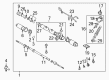
Toyota Solara Rack And Pinion
Choose genuine Rack And Pinion that pass strict quality control tests. You can trust the top quality and lasting durability. Shopping for OEM Rack And Pinion for your Toyota Solara? Our website is your one-stop destination. We stock an extensive selection of genuine Toyota Solara parts. The price is affordable so you can save more. It only takes minutes to browse and find the exact fit. Easily add to cart and check out fast. Our hassle-free return policy will keep you stress-free. We process orders quickly for swift delivery. Your parts will arrive faster, so you can get back on the road sooner.
Toyota Solara Rack And Pinion Parts and Q&A
- Q: How to service and repair the Rack And Pinion on Toyota Solara?A:Start the Rack And Pinion assembly repair by clamping it in a vise using Special Service Tool: 09612-00012 without excessive force application. Detach the 2 turn pressure tubes through the use of Special Service Tool: 09633-00020 while also removing the four O-rings. Initiate service by marking the tie rod end with the rack end along with both lock nuts. Once marked loose the right-hand (RH) and left-hand (LH) lock nuts and tie rod ends followed by the opposite side. To extract the RH and LH clips plus rack boots along with clamps proceed by loosing both clamps using a screwdriver yet handle the boots with great attention to avoid damage. The RH and LH rack ends can be extracted with Special Service Tool: 09922-10010 when you stake back the washer with a screwdriver and hammer while maintaining marking the ends. Use tool 09922-10010 to detach the rack guide spring cap lock nut followed by the rack guide spring cap removal using tool 09631-10021 allowing access to extract the rack guide spring and rack guide and rack guide seat one after the other. Stop the control valve shaft from rotating by using Special Service Tool: 09616-00010 to unload the rack housing cap and self-locking nut. Remove the control valve housing together with its dust cover by marking all positions so you can rebuild correctly. Press the control valve assembly with oil seal out carefully while maintaining oil seal lip integrity and remove the oil seal from the assembly. First mark both the rack housing No. 2 bracket and its grommet before separating the clamp and extracting the grommet. Thus, you should use Special Service Tool: 09631-10021 to rotate the cylinder end stopper first clockwise then counterclockwise until it releases. Then use a brass bar with a hammer to tap out the rack and pinion while removing both the bushing and O-ring. The procedure requires Special Service Tool: 09950-60010 (09951-00290), 09950-70010 (09951-07360) for pressing out the oil seal. The rack and pinion should undergo an inspection for runout and wear while maximum runout must never exceed 0.30 mm (0.0118 inch). Insert the new oil seal after coating its lip with power steering fluid using Special Service Tool: 09950-60010 (09951-00250) and 09950-70010 (09951-07200). Replace any bearings as needed and treat them with molybdenum disulfide lithium base grease. Replace the oil seal from the bushing only if necessary maintaining a damage-free condition while installing an oriented new oil seal. Install a new O-ring which received power steering fluid coating before you expand and place it into the rack and pinion. To construct the control valve assembly install fresh 4 teflon rings that you should expand before coating them with power steering fluid and setting them precisely. Assemble the parts with power steering fluid or molybdenum disulfide lithium base grease when indicated according to the specifications before installing the oil seal with proper orientation followed by inserting the rack and pinion into the housing without damaging the oil seal lip. First install the bushing with an O-ring placed correctly before installing the cylinder end stopper which contains a new wire. Use Special Service Tool: 09631-12071 to test the rack housing for air tightness by creating 53 kPa pressure vacuum for 30 seconds that must remain stable. Position the rack housing No. 2 grommet with its bracket by aligning matchmarks then secure the clamp. Installer the control valve assembly by protecting the oil seal lip, and use Special Service Tool: 09612-22011 to press in the seal. Put the control valve housing together with its assembly while placing the gasket correctly then torque the bolts to 18 Nm (185 kgf-cm, 13 ft. lbs.). The installation process includes using Special Service Tool: 09616-00010 to fasten the self-locking nut with 25 Nm (250 kgf-cm, 18 ft. lbs.) torque. Apply sealant to the threads before torquing the dust cover and rack housing cap to 59 Nm (600 kgf-cm, 43 ft. lbs.). Perform stake operation on the cap parts. Sealant must be applied to rack guide spring cap threads before installing the rack guide seat, rack guide, rack guide spring and rack guide spring cap. Use the RH and LH rack ends during a preload adjustment step by torquing the rack guide spring cap to 25 Nm (250 kgf-cm, 18 ft. lbs.), then return the cap 12 degrees. Adjust the cap tightness when turning the control valve shaft until the spring stops working before finalizing the preload range to 0.8 - 1.4 Nm (8 - 14 kgf-cm, 6.9 - 12.2 inch lbs.). Place the rack guide spring cap lock nut with sealant and torque it to 50 Newton meters (1233.6 inch pounds) before verifying the total preload again. To complete the installation process, stake the washer by ensuring proper alignment before torquing rack ends to 60 Nm (615 kgf-cm, 45 ft. lbs.). Then install RH and LH rack boots along with clamps and clips while checking for no grease in the rack and pinion hole, tighten clamps, and install clips. Apply the following procedure to install the 2 turn pressure tubes with new O-rings and torque to 10 Nm (102 kgf-cm, 7 ft. lbs.).
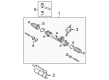
- Q: How to install the rack and pinion power steering gear assembly on Toyota Solara?A:The rack and pinion power steering rack and pinion assembly needs installation with 2 bolts and nuts that require torquing to 70 Nm (714 kgf-cm, 52 ft-lbf). The power steering rack housing heat insulator installation requires the connection of the pressure feed tube assembly through the use of Special Service Tool: 09023-12701 while the torque should be 22 Nm (227 kgf-cm, 16 ft-lbf) at a 300 mm (11.81 in.) fulcrum length for the torque wrench set at a 90-degree angle to the tool. Rephrase this procedure for the return tube assembly by maintaining the same torque specifications. The tube clamp with nut on 2AZ-FE needs to be fastened to 9.8 Nm (100 kgf-cm, 87 in-lbf) torque level while 3MZ-FE installations require tube clamp with nut and insulator to reach this torque and then follow to tighten bolt to 9.8 Nm (100 kgf-cm, 87 in-lbf). Lay the stabilizer bar bush No.1 onto the stabilizer bar before screwing the front stabilizer bracket No.1 LH with two bolts at 27 Nm (275 kgf-cm, 20 ft-lbf). Duplicate this installation for the front stabilizer bracket No.1 RH. Begin by installing front stabilizer link assemblies to both LH and RH sides and then proceed to the installation of both tie rod sets. Eventually mount the front wheel while following a torque range of 103 Nm (1050 kgf-cm, 76 ft-lbf). Secure the steering intermediate shaft assembly along its matchmarks with the rack and pinion assembly and fasten the bolt with a torque of 35 Nm (360 kgf-cm, 26 ft-lbf) then bolt B requires identical torque setting. Place hole cover No.2 into hole cover No.1 and submerge the clamp onto hole cover No.1 before tightening bolt A. Complete power steering fluid bleeding before checking fluid leaks and front wheel alignment and examining the center point of the steering wheel.


Related Toyota Solara Parts
 Toyota Solara Power Steering Pump
 Toyota Solara Steering Wheel
 Toyota Solara Drag Link
 Toyota Solara Power Steering Control Valve
 Toyota Solara Power Steering Hose
 Toyota Solara Power Steering Reservoir
 Toyota Solara Rack and Pinion Boot
 Toyota Solara Steering Column
 Toyota Solara Steering Column Cover
 Toyota Solara Steering Gear Box
 Toyota Solara Steering Shaft
 Toyota Solara Tie Rod End