×
ToyotaParts- Hello
- Login or Register
- Quick Links
- Live Chat
- Track Order
- Parts Availability
- RMA
- Help Center
- Contact Us
- Shop for
- Toyota Parts
- Scion Parts
My Garage
My Account
Cart
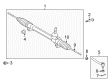
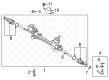
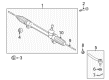
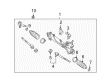
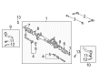
OEM Toyota Highlander Rack And Pinion
Steering Gear- Select Vehicle by Model
- Select Vehicle by VIN
Select Vehicle by Model
orMake
Model
Year
Select Vehicle by VIN
For the most accurate results, select vehicle by your VIN (Vehicle Identification Number).
11 Rack And Pinions found


Toyota Highlander Steering Gear Part Number: 45510-0E030
$628.55 MSRP: $921.15You Save: $292.60 (32%)Ships in 1-3 Business Days

Toyota Highlander Gear Assembly Part Number: 44250-0E040
$711.97 MSRP: $1043.41You Save: $331.44 (32%)
Toyota Highlander Steering Gear Part Number: 45510-0E042
$585.19 MSRP: $857.61You Save: $272.42 (32%)Ships in 1-2 Business DaysToyota Highlander Gear Assembly Part Number: 44250-0E051
$766.45 MSRP: $1123.25You Save: $356.80 (32%)Ships in 1-3 Business DaysToyota Highlander Gear Assembly Part Number: 44250-0E041
$766.45 MSRP: $1123.25You Save: $356.80 (32%)Ships in 1-3 Business Days
Toyota Highlander Link Assembly, Electrical Part Number: 44200-48133
$776.44 MSRP: $1137.89You Save: $361.45 (32%)Ships in 1-3 Business Days
Toyota Highlander Gear Assembly Part Number: 44250-48070
$871.10 MSRP: $1276.61You Save: $405.51 (32%)Ships in 1-3 Business DaysToyota Highlander Gear Assembly Part Number: 44250-0E052
$914.00 MSRP: $1339.48You Save: $425.48 (32%)Ships in 1-2 Business DaysToyota Highlander Gear Assembly Part Number: 44250-0E042
$936.59 MSRP: $1372.58You Save: $435.99 (32%)Ships in 1-2 Business Days
Toyota Highlander Gear Assembly, Power Steering(For Rack & Pinion) Part Number: 44250-0E260
$955.09 MSRP: $1399.70You Save: $444.61 (32%)Ships in 1-2 Business Days
Toyota Highlander Rack And Pinion
Choose genuine Rack And Pinion that pass strict quality control tests. You can trust the top quality and lasting durability. Shopping for OEM Rack And Pinion for your Toyota Highlander? Our website is your one-stop destination. We stock an extensive selection of genuine Toyota Highlander parts. The price is affordable so you can save more. It only takes minutes to browse and find the exact fit. Easily add to cart and check out fast. Our hassle-free return policy will keep you stress-free. We process orders quickly for swift delivery. Your parts will arrive faster, so you can get back on the road sooner.
Toyota Highlander Rack And Pinion Parts and Q&A
- Q: How to remove and replace the Rack And Pinion on Toyota Highlander?A:The beginning of power steering link assembly installation consists of using 2 bolts and nuts that need to be torqued at 70 Nm (714 kgf-cm, 52 ft. lbs.). The installation of the pressure feed tube assembly requires Special Service Tool: 09023-12701 with which to connect the link assembly. The torque should be 22 Nm (230 kgf-cm, 16 ft. lbs.). Finish the installation by tightening the pressure feed tube assembly clamp with a bolt torque of 9.8 Nm (100 kgf-cm, 87 inch lbs.). Use Special Service Tool: 09023-12701 to connect the return tube assembly to the rack and pinion link assembly while torquing to 22 Nm (230 kgf-cm, 16 ft. lbs.). Following this installation secure the tube clamp first to the pressure feed tube assembly before installing and torquing the return tube clamp nut to 9.8 Nm (100 kgf-cm, 87 inch lbs.). Secure stabilizer bar bush No. 1 to the stabilizer bar before fastening stabilizer bracket No. 1 LH and stabilizer bracket No. 2 with two bolts that require torquing to 16 Nm (163 kgf-cm, 12 ft. lbs.). Repeat the procedure to install the front stabilizer bracket No. 1 right-hand side. The installation procedure should connect front stabilizer link assemblies between both LH and RH sides. Place the steering intermediate shaft subassembly matchmarks with the rack and pinion link assembly then bolt the assembly with a torque of 35 Nm (360 kgf-cm, 26 ft. lbs.). Tighten bolt A to the same torque. Fasten the steering column hole cover No. 2 onto the steering hole cover No. 1 followed by installing a clamp on the steering column hole cover No. 1 while tightening bolt B. Afterward, use the same steps to connect the tie rod assemblies on both sides. Follow these steps: Install the front wheel while applying torque of 103 Nm (1,050 kgf-cm, 76 ft. lbs.). To finish the installation bleed the power steering fluid and look for any leakage then check the front wheel alignment, align the steering angle sensor zero point and examine the steering wheel center point.
- Q: How to install the power steering Rack And Pinion on Toyota Highlander?A:Installing the power steering rack and pinion for the 1AR-FE requires first installing the tie rod assembly LH to the steering rack end sub-assembly while matching the marks and torquing the lock nut after toe-in adjustment. Then repeat the same procedure for the tie rod assembly RH. Position the power steering link assembly on the left side of the vehicle before lifting the front stabilizer bar with bracket using the following installation and torques: secure with 2 bolts and 2 nuts totaling 70 Nm torque but tighten the bolt by starting from the left side with the nut stationary. Proceed to install the front stabilizer bar with bracket while performing the installation of the front No. 1 stabilizer bracket LH and torquing it to 29 Nm (296 kgf-cm, 21 ft-lbf). Then move forwards with the front No. 1 stabilizer bracket RH attachment process. The tie rod assembly LH must be connected to the Steering Knuckle using the nut that is torqued to 49 Nm (500 kgf-cm, 36 ft-lbf) followed by installing a new cotter pin while tightening the fastener to a maximum of 60 degrees when the holes are not properly aligned. Repetition of this step should be done for the tie rod assembly on the right-hand side. Attach the matchmarks of the steering intermediate shaft assembly and power steering link assembly before installing the bolt with 35 Nm torque value (357 kgf-cm or 26 ft-lbf). At first install the front stabilizer link assembly LH by tightening it to 74 Nm (755 kgf-cm, 55 ft-lbf) then proceed with installing the front stabilizer link assembly RH under the same torque specifications. Set the front wheels straight ahead after torquing each wheel to 103 Nm before installing the floor under cover LH and No. 2 and No. 1 engine under covers. The inspection and adjustment process for the front wheel alignment should take place as the final step.


Related Toyota Highlander Parts
 Toyota Highlander Steering Wheel
 Toyota Highlander Power Steering Hose
 Toyota Highlander Power Steering Pump
 Toyota Highlander Drag Link
 Toyota Highlander Ignition Switch
 Toyota Highlander Power Steering Reservoir
 Toyota Highlander Rack and Pinion Boot
 Toyota Highlander Shift Interlock Solenoid
 Toyota Highlander Steering Column
 Toyota Highlander Steering Gear Box
 Toyota Highlander Universal Joint
 Toyota Highlander Windshield Wiper Switch